


Getting Started with ESP8266 and Arduino: ESP8266 Arduino Interface
If you are into IoT (Internet of Things), you might have heard of ESP8266 WiFi Module. If not, do not worry. This tutorial is about getting started with Esp8266 WiFi Module and how the ESP8266 Arduino pair can be used in your IoT Projects.
So, before going into the details of how to interface the ESP8266 Arduino Pair, let’s get started with ESP8266 WiFi Module first.
Take a look at these INTERNET OF THINGS (IOT) PROJECTS.
What is ESP8266?
ESP8266 (technically ESP8266EX) is a WiFi Module based on Cadence Tensilica L106 32-bit MCU manufactured by Espressif Systems. The ESP8266 SoC contains a fully functional WiFi Stack and TCP/IP Stack that allows any Microcontroller to get connected to WiFi Network.
With Software Development Kits (SDKs), you can directly program the ESP8266’s on-chip Microcontroller, without the need for an external Microcontroller.
Based on the ESP8266 SoC, several third party manufacturers started manufacturing custom boards and one such manufacturer is Ai-Thinker. The first board manufactured by Ai-Thinker is ESP-01 (which is the same board used in this project) and it became quite popular.
Based on the success of the ESP-01 Module, several other modules like ESP-02, ESP-07, ESP-12, etc. were released by Ai-Thinker. All these boards are based on ESP8266 SoC but the main difference is the number of GPIO Pins.
There are other modules like ESP-WROOM by Espressif Systems, NodeMCU, WeMOS, SparkFun ESP8266, etc.
ESP8266 ESP-01
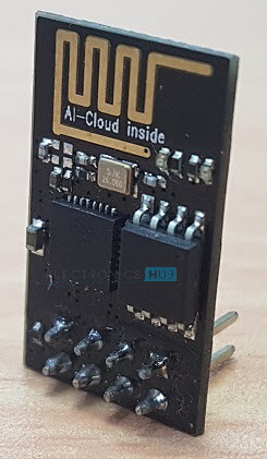
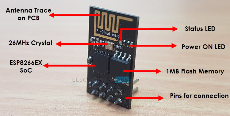
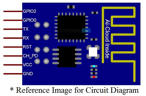
In this project, we will be using the Ai-Thinker’s ESP-01 Module. It consists of 8 pins and the following image shows the different components of the board.
Coming to the pin configuration, as mentioned above, the ESP-01 module consists of 8 pins and these pins are VCC, GND, TX, RX, RST, CH_PD, GPIO0 and GPIO2. The following image shows the pin diagram of the ESP-01 Module.
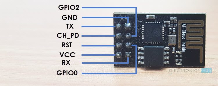
Pin Description of ESP8266 ESP-01 Module
- VCC: It is the power pin through which 3.3V is supplied.
- GND: It is the ground pin.
- TX: This pin is used to transmit serial data to other devices.
- RX: The RX pin is used to receive serial data from other devices.
- RST: It is the Reset Pin and it is an active LOW Pin. (ESP8266 will reset if the RST pin receives LOW signal).
- CH_PD: This is the chip enable pin and it is an active HIGH Pin. It is usually connected to 3.3V.
- GPIO0: The GPIO0 (General Purpose I/O) Pin has dual functions – one for normal GPIO Operation and other for enabling the Programming Mode of ESP8266.
- GPIO2: This is GPIO Pin.
IMPORTANT NOTE: The ESP8266 is not compatible with 5V and the ESP-01 Module does not have any voltage regulators on-board. Make sure that the power supply to the ESP8266 is 3.3V, preferably from a dedicated power supply rather than taking it from the 3.3V Pin of the Arduino.
ESP8266 Arduino Interface
Before seeing the ESP8266 Arduino Interface, you need to know a few things about the ESP8266 Module. The ESP8266 WiFi Module comes with default firmware which supports AT commands.
After interfacing the ESP8266 WiFi Module with Arduino and uploading our own program, the original firmware will be erased. We will see in a separate project on how to interface ESP8266 Module for AT Commands and also how to flash the original firmware using Arduino.
Now, we will see how to program ESP8266 using Arduino and access its GPIO pins. First, we will see the circuit diagram of the interface.
Circuit Diagram of ESP8266 Arduino Interface
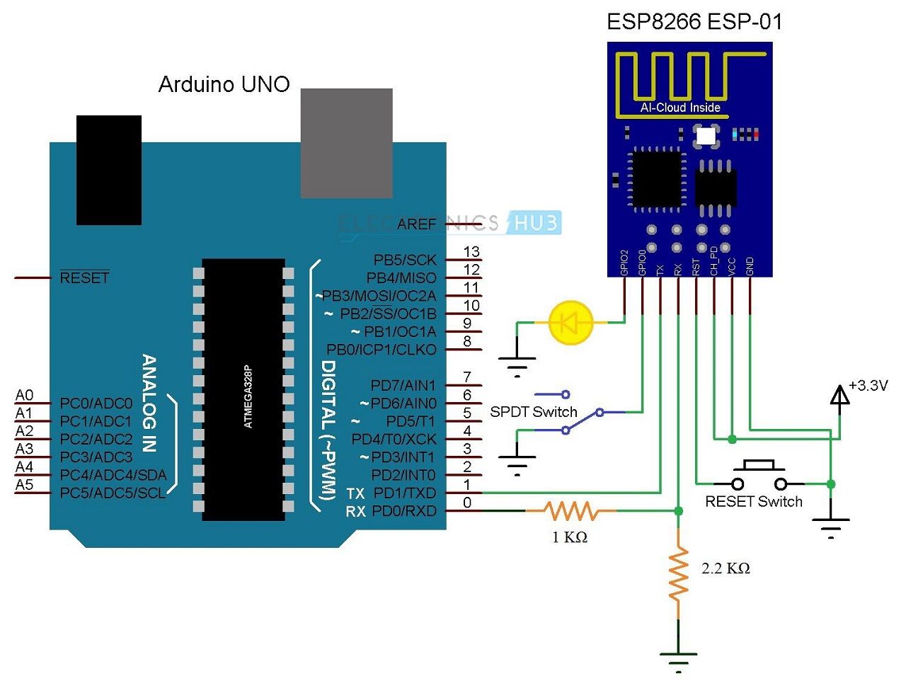
If the ESP8266 Module in the circuit diagram is not clear, the following image might help you. It is just a personal representation for circuit diagram. You have already seen actual pin diagram in the previous section.
Components Required
- Arduino UNO [Buy Here]
- ESP8266 ESP-01
- 1 KΩ Resistor
- 2.2 KΩ Resistor
- 100 pF Capacitor (Capacitor Code 104)
- Mini Breadboard
- Connecting Wires
Getting the ESP8266 ESP-01 Module Ready for Breadboard Mount
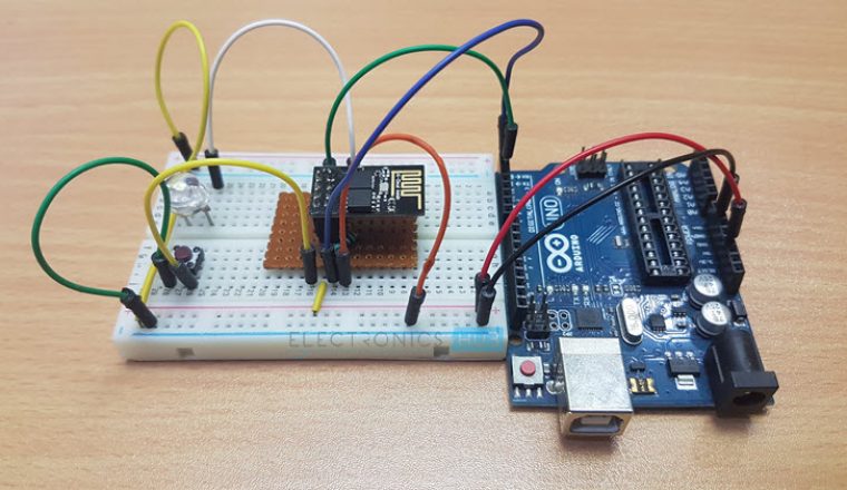
If you take a look at the Pins of the ESP8266 ESP-01 Module, you can observe that it is not breadboard friendly. So, I have made a small perf board with breadboard friendly pins on the bottom and female headers to mount the ESP8266 ESP-01 Module on it.
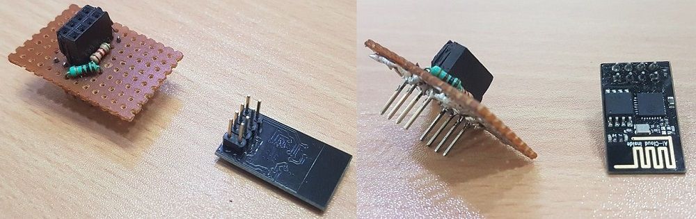
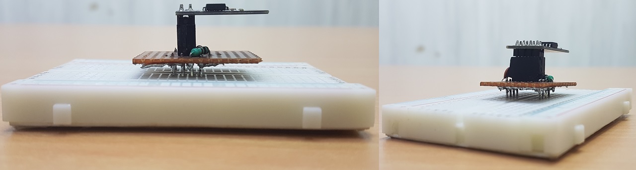
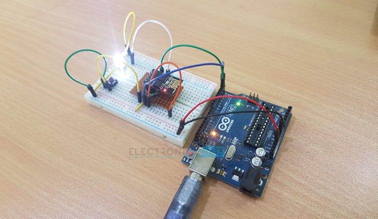
On this perf board, I’ve also connected the level converter resistors for RX Pin of the ESP8266 and also a 100 pF Bypass Capacitor between VCC (3.3V) and GND. The following image shows the mounting of ESP8266 ESP-01 Module on a mini breadboard.

Getting Arduino IDE Ready for Programming ESP8266
ESP8266 WiFi Module can be programmed using Arduino IDE and in order to do that you need to make a few changes to the Arduino IDE. First, go to File Preferences in the Arduino IDE and in the Additional Boards Manager URLs Section, enter the following URL.
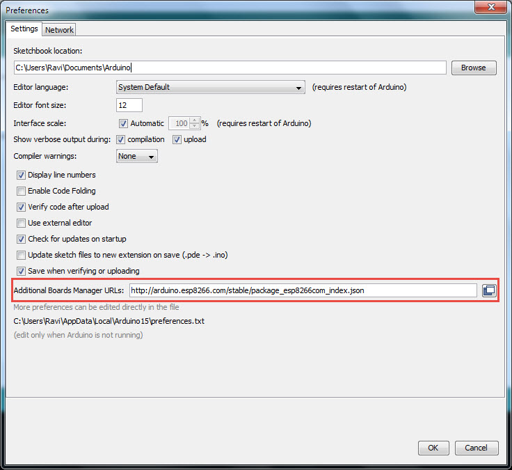
NOTE: You can add many such URLs but they must be separated with commas.
Now, go to Tools Board Boards Manager and search for ESP8266 in the search field. Select the ESP8266 by ESP8266 Community and click on Install.
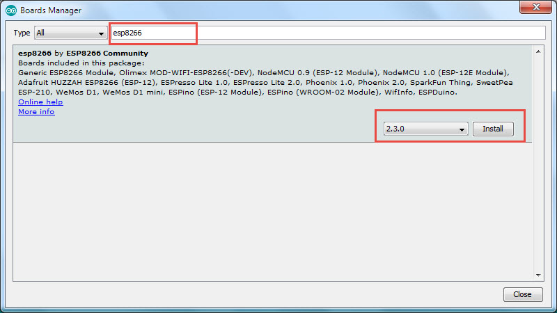
NOTE: This feature of adding third-party boards through board manager is available for Arduino IDE Version 1.6.4 and higher. So, make sure that you have the latest version of Arduino IDE.
Getting Arduino UNO Ready for Programming ESP8266
In order to Program ESP8266 Module, we need to connect it to a computer. Since Serial Communication is the only available communication on the ESP8266 ESP-01 Module, we need an USB to Serial Adapter like an FTDI, CH340 or FT232RL.
If you do not have a dedicated USB to Serial Adapter, do not worry. The Arduino UNO has an on-board USB to Serial Adapter (which is used to program the Arduino). We are going to use this for programming the ESP8266.
We will be using the TX and RX Pins of the Arduino to connect to the ESP8266 Module and in order to make sure that Arduino isn’t using those pins, we can upload a bare minimum sketch to Arduino.
NOTE: Bare minimum sketch consists of just the setup and loop functions without any data in them.
In my case, I have an extra Arduino UNO Board with a non-functioning ATmega328p IC. So, I removed the Microcontroller IC from the Arduino UNO and started using it as an USB to Serial Converter.
Circuit Design for Programming ESP8266 using Arduino
You have already seen the required components and the circuit diagram of the project. Now, let us try to understand the design of the circuit.
First and foremost, the ESP8266 Module works on 3.3V Power Supply and anything greater than that, like 5V for example, will kill the SoC. So, the VCC Pin and CH_PD Pin of ESP8266 ESP-01 Module are connected to a 3.3V Supply.
Next important thing to remember is that the ESP8266 WiFi Module has two modes of operation: Programming Mode and Normal Mode.
In Programming Mode, you can upload the program or firmware to the ESP8266 Module and in Normal Mode, the uploaded program or firmware will run normally.
In order to enable the Programming Mode, the GPIO0 pin must be connected to GND. In the circuit diagram, I’ve connected a SPDT switch to the GPIO0 pin. Toggling the lever of SPDT will switch the ESP8266 between Programming mode (GPIO0 is connected to GND) and normal mode (GPIO0 acts as a GPIO Pin).
Also, the RST (Reset) will play an important role in enabling Programming Mode. The RST pin is an active LOW pin and hence, it is connected to GND through a Push Button. So, whenever the button is pressed, the ESP8266 Module will reset.
The RX and TX pins of the ESP8266 Module are connected to RX and TX Pins on the Arduino board. Since the ESP8266 SoC cannot tolerate 5V, the RX Pin of Arduino is connected through a level converter consisting of a 1KΩ and a 2.2KΩ Resistor.
Finally the GPIO2 pin is connected to an LED to test the working of the program. All the necessary connections for enabling the Programming Mode in ESP8266 are mentioned below.
- VCC 3.3V
- GND GND
- CH_PD 3.3V
- RST Normally Open; GND to Reset
- GPIO0 GND
- TX TX of Arduino
- RX RX of Arduino (through level converter)
Working of ESP8266 Arduino Interface
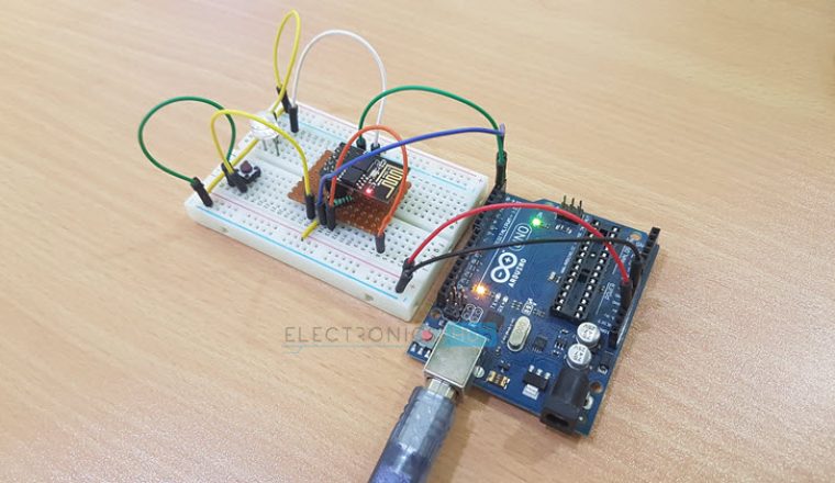
Make sure that all the above mentioned connections are properly made. After connecting and configuring the ESP8266 in Programming Mode (GPIO0 is connected to GND), connect the Arduino to the system.
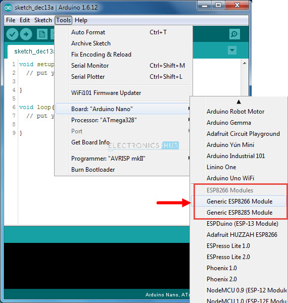
Once the ESP8266 Module is powered ON, Push the RST button and open the Arduino IDE. In the Board options (Tools Board), select the “Generic ESP8266” Board. Select the appropriate port number in the IDE.
Now, open the Blink Sketch and change the LED Pin to 2. Here, 2 means GPIO2 pin of the ESP8266 Module. Before you hit the upload make sure that GPIO0 is connected to GND first and then press the RST button.
Hit the upload button and the code will take a while to compile and upload. You can see the progress at the bottom of the IDE. Once the program is successfully uploaded, you can remove the GPIO0 from GND. The LED connected to GPIO2 will blink.
In this project, we have seen how the ESP8266 Arduino Interface will work, how to upload a program into the ESP8266 WiFi Module and access the Input/Output Pins of the ESP8266 Module.
Источник: