


PIR Motion Sensor
Содержание
You will be redirected back to this guide once you sign in, and can then subscribe to this guide.
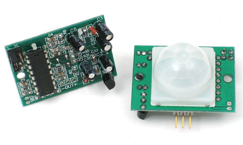
PIRs are basically made of a pyroelectric sensor (which you can see below as the round metal can with a rectangular crystal in the center), which can detect levels of infrared radiation. Everything emits some low level radiation, and the hotter something is, the more radiation is emitted. The sensor in a motion detector is actually split in two halves. The reason for that is that we are looking to detect motion (change) not average IR levels. The two halves are wired up so that they cancel each other out. If one half sees more or less IR radiation than the other, the output will swing high or low.

Along with the pyroelectic sensor is a bunch of supporting circuitry, resistors and capacitors. It seems that most small hobbyist sensors use the BISS0001 ("Micro Power PIR Motion Detector IC"), undoubtedly a very inexpensive chip. This chip takes the output of the sensor and does some minor processing on it to emit a digital output pulse from the analog sensor.
Our older PIRs looked like this:

These stats are for the PIR sensor in the Adafruit shop which is very much like the Parallax one . Nearly all PIRs will have slightly different specifications, although they all pretty much work the same. If there’s a datasheet, you’ll want to refer to it
- Size: Rectangular
- Price:$10.00 at the Adafruit shop
- Output: Digital pulse high (3V) when triggered (motion detected) digital low when idle (no motion detected). Pulse lengths are determined by resistors and capacitors on the PCB and differ from sensor to sensor.
- Sensitivity range: up to 20 feet (6 meters) 110° x 70° detection range
- Power supply: 5V-12V input voltage for most modules (they have a 3.3V regulator), but 5V is ideal in case the regulator has different specs
- BIS0001 Datasheet(the decoder chip used)
- RE200B datasheet(most likely the PIR sensing element used)
- NL11NH datasheet(equivalent lens used)
- Parallax Datasheet on their version of the sensor
How PIRs Work
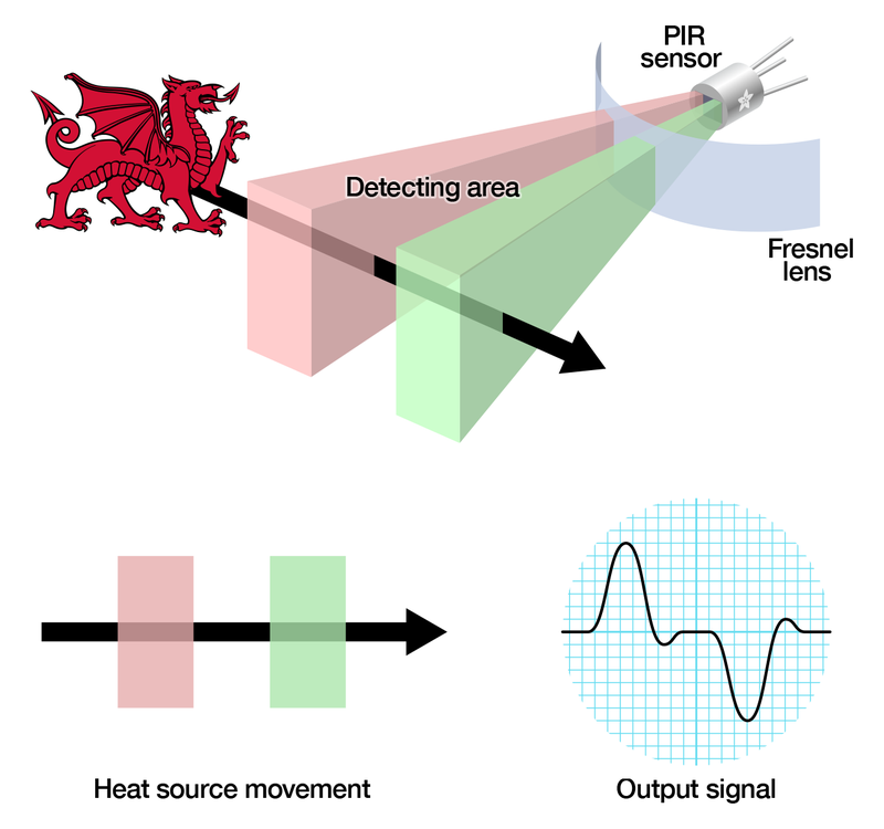
PIR sensors are more complicated than many of the other sensors explained in these tutorials (like photocells, FSRs and tilt switches) because there are multiple variables that affect the sensors input and output. To begin explaining how a basic sensor works, we’ll use this rather nice diagram
The PIR sensor itself has two slots in it, each slot is made of a special material that is sensitive to IR. The lens used here is not really doing much and so we see that the two slots can ‘see’ out past some distance (basically the sensitivity of the sensor). When the sensor is idle, both slots detect the same amount of IR, the ambient amount radiated from the room or walls or outdoors. When a warm body like a human or animal passes by, it first intercepts one half of the PIR sensor, which causes a positive differential change between the two halves. When the warm body leaves the sensing area, the reverse happens, whereby the sensor generates a negative differential change. These change pulses are what is detected.
You can see above the diagram showing the element window, the two pieces of sensing material
This image shows the internal schematic. There is actually a JFET inside (a type of transistor) which is very low-noise and buffers the extremely high impedence of the sensors into something a low-cost chip (like the BIS0001) can sense.
In the diagram up top, the lens is just a piece of plastic, but that means that the detection area is just two rectangles. Usually we’d like to have a detection area that is much larger. To do that, we use a simple lens such as those found in a camera: they condenses a large area (such as a landscape) into a small one (on film or a CCD sensor). For reasons that will be apparent soon, we would like to make the PIR lenses small and thin and moldable from cheap plastic, even though it may add distortion. For this reason the sensors are actually Fresnel lenses:
The Fresnel lens condenses light, providing a larger range of IR to the sensor.

OK, so now we have a much larger range. However, remember that we actually have two sensors, and more importantly we dont want two really big sensing-area rectangles, but rather a scattering of multiple small areas. So what we do is split up the lens into multiple section, each section of which is a fresnel lens.


This macro shot shows the different Fresnel lenses in each facet!
The different faceting and sub-lenses create a range of detection areas, interleaved with each other. That’s why the lens centers in the facets above are ‘inconsistent’ — every other one points to a different half of the PIR sensing element
Here is another image, more qualitative but not as quantitative. (Note that the sensor in the Adafruit shop is 110° not 90°)
Connecting to a PIR

Most PIR modules have a 3-pin connection at the side or bottom. The pinout may vary between modules so triple-check the pinout! It’s often silkscreened on right next to the connection (at least, ours is!) One pin will be ground, another will be signal and the final one will be power. Power is usually 3-5VDC input but may be as high as 12V. Sometimes larger modules don’t have direct output and instead just operate a relay in which case there is ground, power and the two switch connections.
The output of some relays may be ‘open collector’ — that means it requires a pullup resistor. If you’re not getting a variable output be sure to try attaching a 10K pullup between the signal and power pins.
An easy way of prototyping with PIR sensors is to connect it to a breadboard since the connection port is 0.1" spacing. Some PIRs come with header on them already, the one’s from adafruit have a straight 3-pin header on them for connecting a cable

Testing a PIR
Now when the PIR detects motion, the output pin will go "high" to 3.3V and light up the LED!
Once you have the breadboard wired up, insert batteries and wait 30-60 seconds for the PIR to ‘stabilize’. During that time the LED may blink a little. Wait until the LED is off and then move around in front of it, waving a hand, etc, to see the LED light up!
There’s a couple options you may have with your PIR. First up we’ll explore the ‘Retriggering’ option.
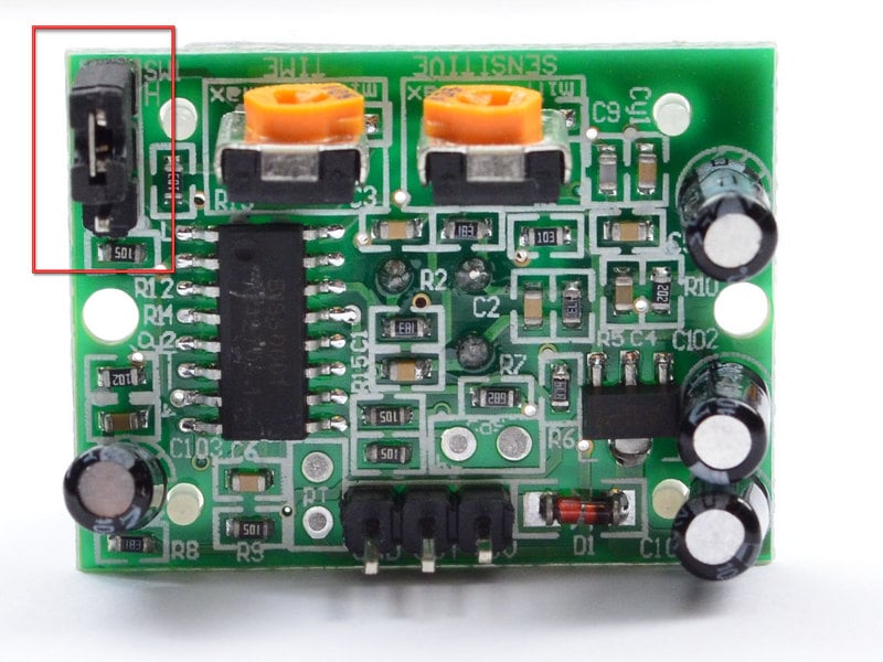
Once you have the LED blinking, look on the back of the PIR sensor and make sure that the jumper is placed in the L position as shown below.


(The graphs above are from the BISS0001 datasheet, they kinda suck)
For most applications, "retriggering" (jumper in H position as shown below) mode is a little nicer.

There are two ‘timeouts’ associated with the PIR sensor. One is the "Tx" timeout: how long the LED is lit after it detects movement — this is easy to adjust on Adafruit PIR’s because there’s a potentiometer.
The second is the "Ti" timeout which is how long the LED is guaranteed to be off when there is no movement. This one is not easily changed but if you’re handy with a soldering iron it is within reason.
First, lets take a look at the BISS datasheet again
Determining R10 and R9 isnt too tough. Unfortunately this PIR sensor is mislabeled (it looks like they swapped R9 R17). You can trace the pins by looking at the BISS001 datasheet and figuring out what pins they are — R10 connects to pin 3 and R9 connects to pin 7. the capacitors are a little tougher to determine, but you can ‘reverse engineer’ them from timing the sensor and solving!
1.2 seconds
R10 = 4.7K and C6 = 10nF
1.2 seconds
R9 = 470K and C7 = 0.1uF
You can change the timing by swapping different resistors or capacitors. For a nice tutorial on this, see Keith’s PIR hacking page.
Источник: