


055251 Nano FT232 Starter Kit
Содержание
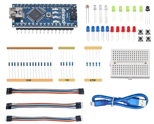
Containing resistors with different resistance values, different colors LEDs, buttons and IR receiving components, this kit is compatible with various Nanocontrollers and Raspberry Pi. Compatible with the Arduino development platform, the Nano control board belongs to the Arduino series Nanocontroller. To make you have a better understanding with these components and Nano control board, we will also provide some learning courses based on the Arduino, like wiring methods, test code, etc.
Component List
| No. | Product Name | Quantity | Picture |
|---|---|---|---|
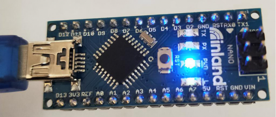
| 1 | Main Board Nano | 1 | 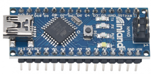 |
| 2 | USB mini B Cable | 1 | 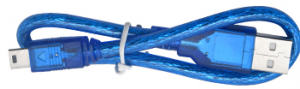 |
| 3 | 220Ω resistor | 15 | 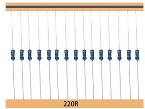 |
| 4 | 470Ω resistor | 5 | 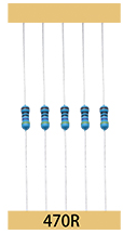 |
| 5 | 10KΩ resistor | 5 | 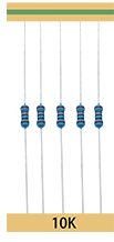 |
| 6 | LED — Green | 5 | 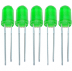 |
| 7 | LED — Blue | 5 | 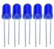 |
| 8 | LED — Red | 5 | 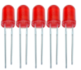 |
| 9 | F5- full-color RGB | 5 | 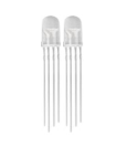 |
| 10 | Dupont Line | 10 | |
| 11 | Dupont Line | 10 | |
| 12 | Dupont Line | 10 | |
| 13 | button | 4 |  |
| 14 | Breadboard | 2 | 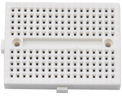 |
| 15 | Photo Resistor | 3 | |
| 16 | IR emitter | 1 | |
| 17 | IR receiver | 1 |
Installing Arduino IDE And Driver
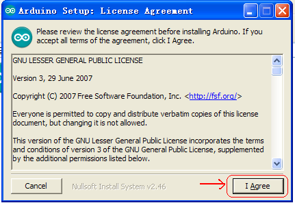
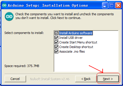
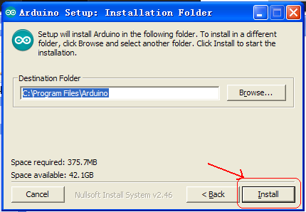
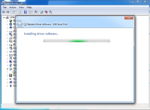
When we get the development board, we firstly need to install the Arduino IDE and driver. The related files can be found on the official website. The following links you could refer to: https://www.arduino.cc/en/Main/OldSoftwareReleases#1.5.x Next to introduce installation method of Arduino-1.5.6 version IDEfor Windows system. Download arduino-1.5.6-r2-windows.zip compressed folder and unzip it. Double click Arduino-1.5.6 .exe file
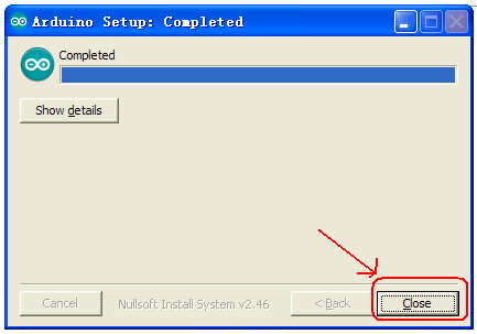
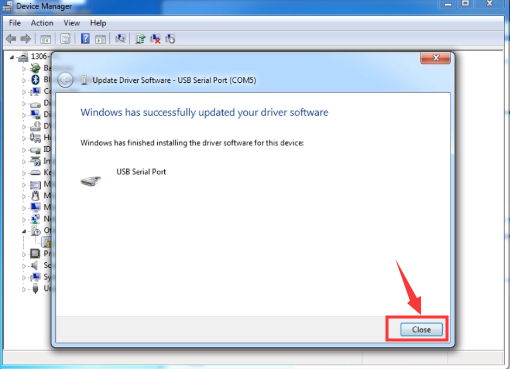
Complete driver installation, click “Close” as shown below

Next to install Nano control board. This Nano board uses FT232 USB chip, so we need to install driver compatible with FT232 chip. Connect Nano control board to the computer. Click Computer—Properties—Device Manager, as shown below.
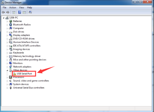
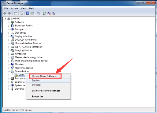
Click “USB Serial Port” to install driver, as shown below.
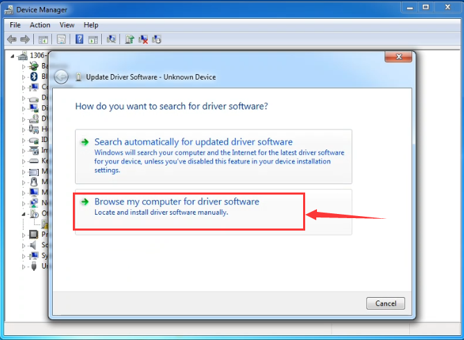
Enter the following page.
Find ft232r usb uart Driver folder.
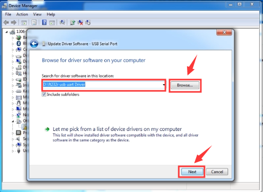
Click“Next ” to start installing.
Finish installing, click to “close”
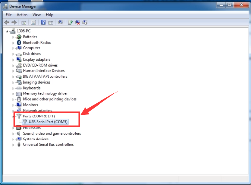
The driver is now installed. Click Computer-Properties-Device Manager, as shown below:
Project
Hello World!
Description
After installing USB driver of Nano control board, we can find the corresponding serial port in Windows Device Manager. The burning of the first program is shown below. The serial monitor shows "Hello world!".
Wiring Diagram
Test Result
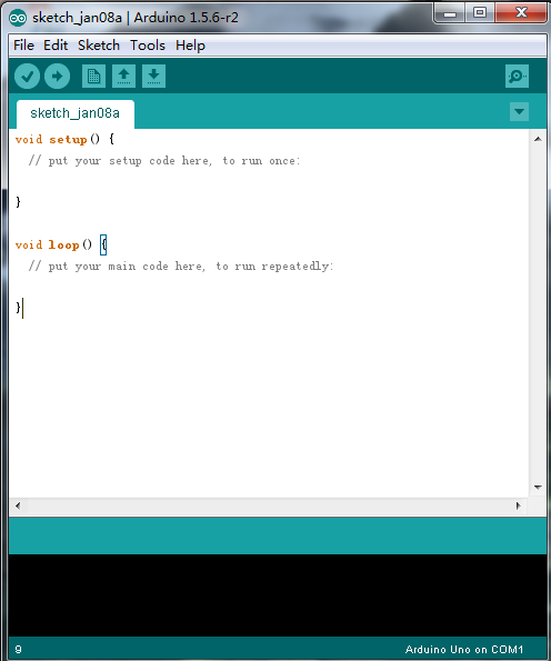
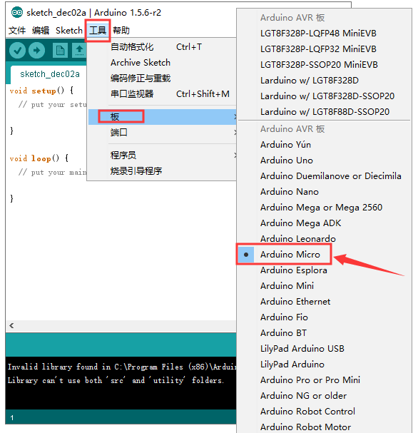
Open Arduino software, set board as shown below.
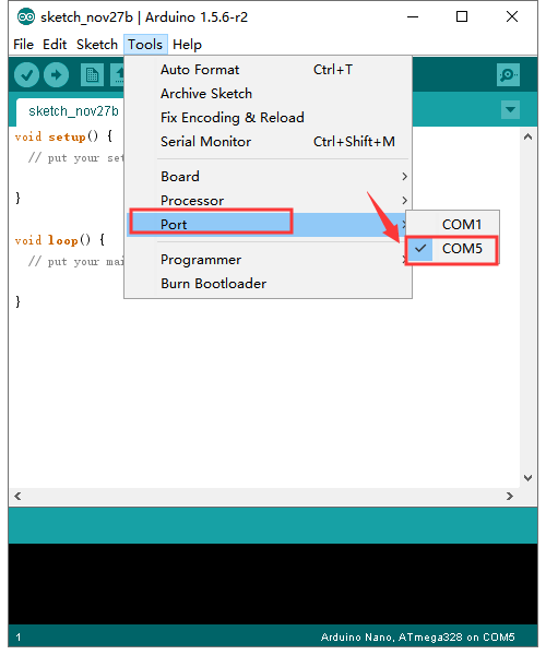
Set COM port, as shown below.
Click![]() to compile the program,check if the program is right;click
to compile the program,check if the program is right;click ![]() to upload program;after setting up Nano control board, as shown below:
to upload program;after setting up Nano control board, as shown below: 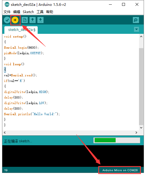
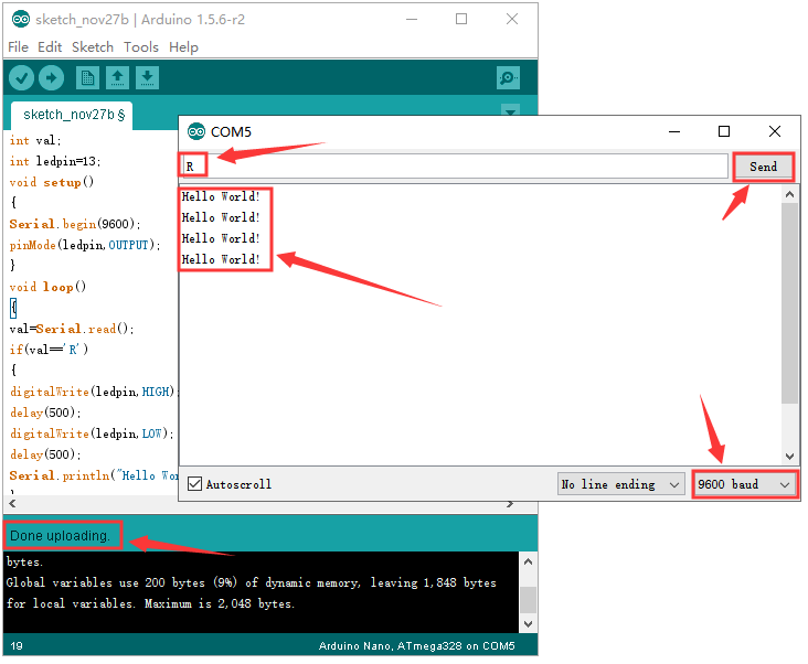
Upload successfully,enter “R”,click to “send”, the indicator of D13 blinks once on the Nano control board, serial monitor displays “ Hello World!”
Congratulation! Upload successfully!
LED Blinking
Description
The blinking LED experiment is quite simple. In this experiment, we’ll complete experiment using other digital I/O ports and external light.
- Nano control board*1
- USB cable*1
- LED*1
- 220Ω Resistor*1
- Breadboard*1
- Male to female Dupont Lines
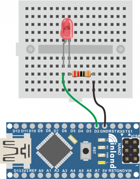
Wiring Diagram
Test Result
After downloading program, you will see the LED connected to IO port blinking, with an interval approximately one second. The blinking LED experiment is now completed.
Advertising Lights
Description
In life, we often see some billboards composed of colorful led lights. Different effects shown on billboard as lights change. In this section, we simulate the effect of advertising lights with LED lights.
- Nano control board*1
- USB cable*1
- LED*5
- 220Ω Resistor*5
- Breadboard*1
- Male to female Dupont Lines
- Male to male Dupont Lines
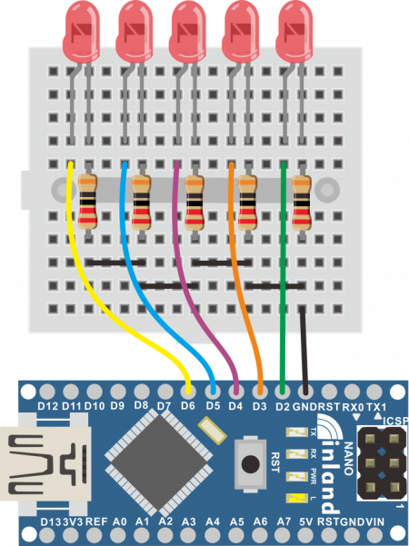
Test Result
After downloading the program, the external small light gradually brightens then darkens, and alternates.
Button-controlled LED
Description
I/O port means interface for INPUT and OUTPUT. Up until now, we’ve only used the output function. In this experiment, we will try to use the input function, which is to read the output value of device. We’ll complete an experiment with use 1 button and 1 LED to give you a better understanding of the I/O function.
- Nano control board*1
- USB cable*1
- LED*1
- Button *1
- 220Ω Resistor*1
- 10KΩ Resistor*1
- Breadboard*1
- Male to female Dupont Lines
- Male to male Dupont Lines
Wiring Diagram
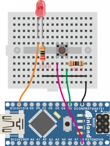
Test Result
After downloading the program and powering on, the LED light is on when the button is pressed, otherwise it is off.
RGB LED
Description
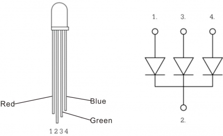
RGB lights can adjust the intensity of three primary colors (red / blue / green) through the PWM voltage input of the three pins R, G, and B to achieve the full-color mixing effect. In this experiment, we control the RGB lights to display different colors by controlling the PWM values of the three PWM ports. The description of the RGB light interfaces are shown below.
- Nano control board*1
- USB cable*1
- RGB LED*1
- 220Ω Resistor*3
- Breadboard*1
- Dupont Lines
- Breadboard cables
Wiring Diagram
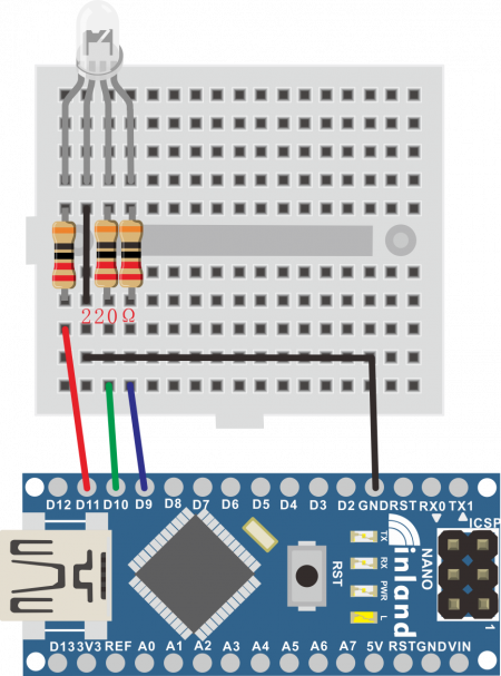
Test Result
After downloading the program and powering on, the external RGB light displays various colors alternately.
Источник: