


Arduino Micro Pinout, Specifications, Schematic datasheet
Содержание
- Introduction to Arduino Micro:
- Arduino Micro Pinout:
- Specifications of Arduino Micro:
- Arduino Micro Schematic :
- Atmega32U4 Datasheet:
- Arduino Micro Dimensions/ board size :
The Arduino Micro is a miniature version of the Arduino Leonardo board. It has an ATmega32U4 microcontroller at its heart. And the board features 20 digital input/output pins , a 16 MHz crystal oscillator , a micro-USB port , an ICSP header pins , and a RESET button . Arduino Micro pinout, specifications, schematic, and datasheet is given below.
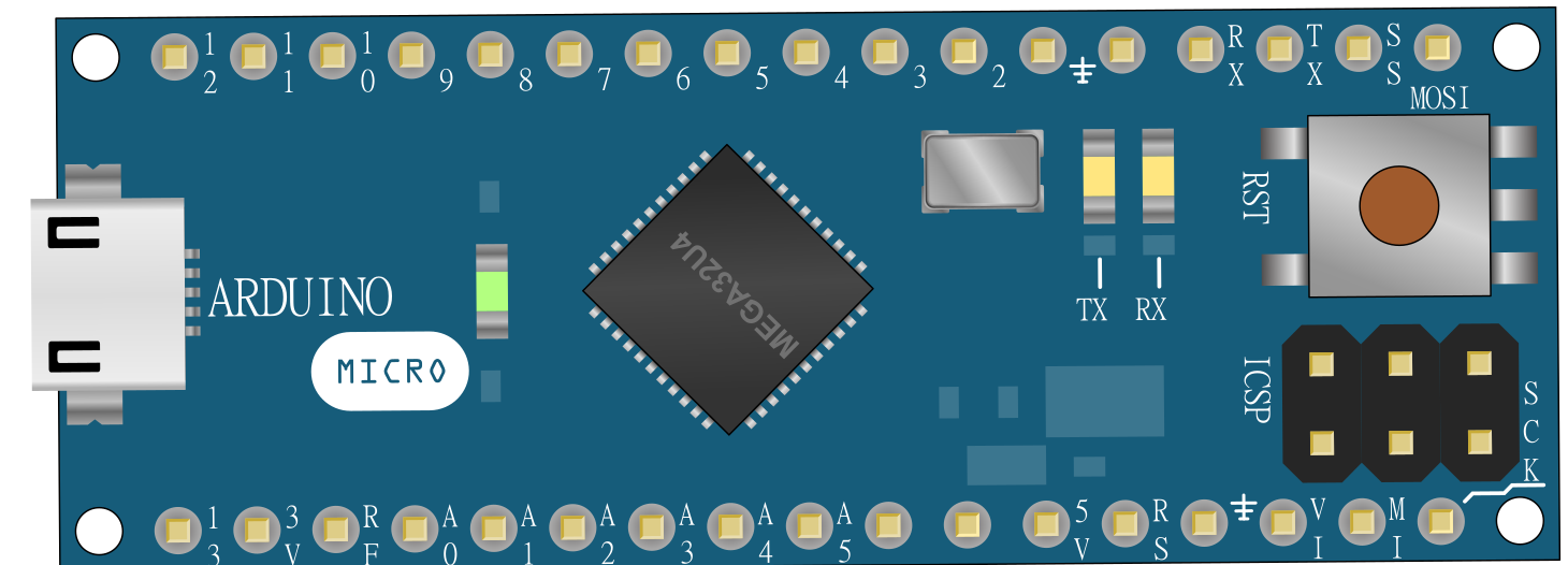
Front View of Arduino Micro
Introduction to Arduino Micro:
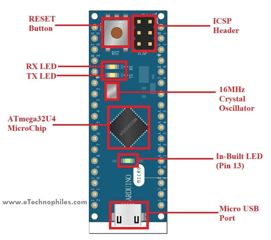
Introduction to Arduino Micro parts
Atmega32U4 : The ATMega32U4 microcontroller chip is developed by Atmel. It is a low-power 8-bit AVR RISC -based microchip that features a 32KB self-programming flash program memory, 2.5KB SRAM , 1KB EEPROM , USB 2.0 full-speed/low-speed device, 12-channel 10-bit A/D-converter , and JTAG interface for on-chip-debug.
Atmega32U4 pinout : The atmega32U4 microcontroller chip has 44 pins and comes in a TQFP package.
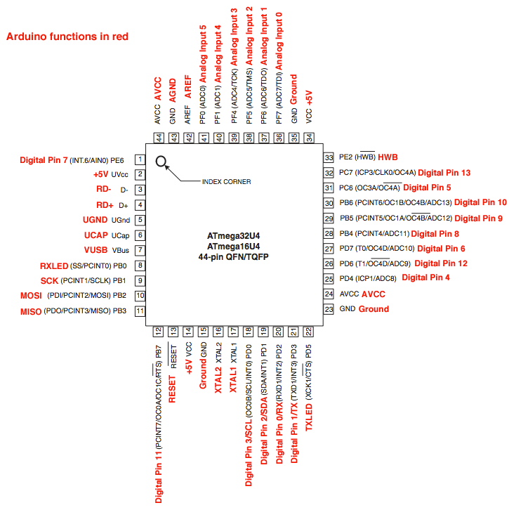
Atmega32U4 pinout
Crystal Oscillator : The Arduino Micro board comes with a crystal oscillator of frequency16MHz, which generates the clock signal in the microcontroller. The basic function of the crystal oscillator is to provide the basic timing and control to the board.
Micro USB Port : The Arduino Micro comes with a Micro USB 2.0 port. It allows us to bridge the connection between the board and the computer. It is very crucial for programming the Arduino Micro board.
Note : The Arduino Micro has a fuse connected to the USB port. It protects the computer’s USB ports from overcurrent and shorts, in case the current of more than 500 mA is drawn from the port. This fuse is a resettable polyfuse that automatically breaks the connection until the short or overload is removed. And once the circuit is free from overcurrent, this resettable polyfus e returns to its original state.
RESET Button : This button is used for resetting the board. It’s recommended to press the reset button after flashing some code to the Arduino Micro.
INBUILT LED (13) : In the Arduino Micro board, there is a built-in LED (Green) connected to the digital pin 13. The LED can be controlled by switching the pin to HIGH or LOW.
RX LED (17): In the board, there is an RX LED connected to digital pin 17. The LED can be controlled by switching the pin to HIGH or LOW.
TX LED (30): In the board, there is a TX LED connected to digital pin 30. The LED can be controlled by switching the pin to HIGH or LOW.
Arduino Micro Pinout:
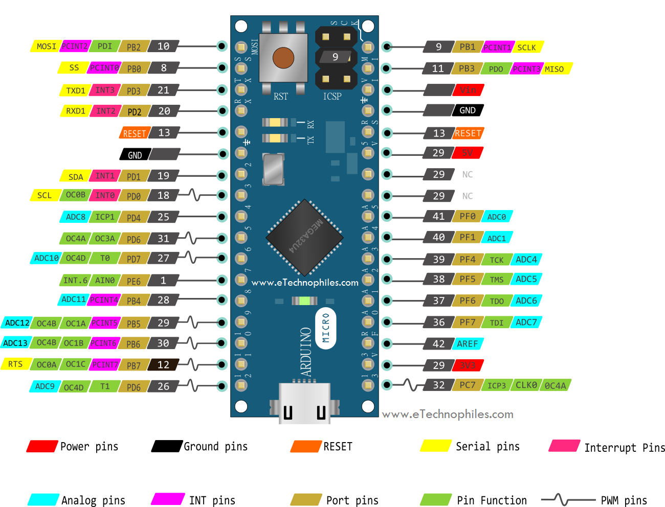
Arduino Micro pinout
- As shown in the Arduino micro pinout above, the board has 20 digital I/O pins. Out of these 20 pins, 7 pins are PWM (Pulse Width Modulation) pins and, 12 pins are analog input pins.
- Apart from this, Arduino Micro has a reset button, 16MHz crystal oscillator, ICSP header, and a micro-USB port.
Power Pins on Arduino Micro :
Vin pin: It is the input voltage pin, which can be used to power up the Arduino board. When a certain voltage is given via the power jack to power the board, this voltage shows up at the Vin pin.
Note : Vin pin and Power jack terminal are connected to each other internally.
5V pin: The 5V pin generates regulated 5v output for the externally connected components. The power source of the 5V pin for the Arduino Micro board is a USB connector and the Vin.
Note : A 5-volt voltage regulator step down the input voltage coming from the Vin pin or power jack to a steady 5V. This 5V output from the voltage regulator is then connected to the 5V pin of Arduino Micro.
3.3 V pin: The 3.3V pin generates an output voltage of 3.3v.
GND pins. Two ground pins are available on Arduino Micro board.
Digital I/O pins:
- There are 20 digital I/O pins on the Arduino Micro board that can be used as an input or output. They operate at 5 volts.
- The Arduino Micro digital pins can read one of the two states: when the electric signal is present and when it is absent. This kind of input is usually known as digital (or binary) and these states are referred to as HIGH and LOW or 1 and 0.
Analog Pins:
- The Arduino Micro consists of 12 analog inputs, labeled as ADCX (where X is pin no.). All of these pins are digital I/O pins also.
- Each one of the analog pins is connected to an inbuilt ADC of 2 10 bit (i.e, 1024 different values) resolution.
PWM pins on Arduino Micro:
- The seven pins from the set of digital pins are PWM (Pulse Width Modulation) pins which are numbered as 3, 5, 6, 9, 10, 11, and 13.
- Each PWM pin provides 8-bit PWM output.
- To generate the PWM output, syntax “ analogwrite(PWM Pin, PWM value) ” is used. PWM value varies between 0 (0 volts) and 255 (5 volts).

UART pins:
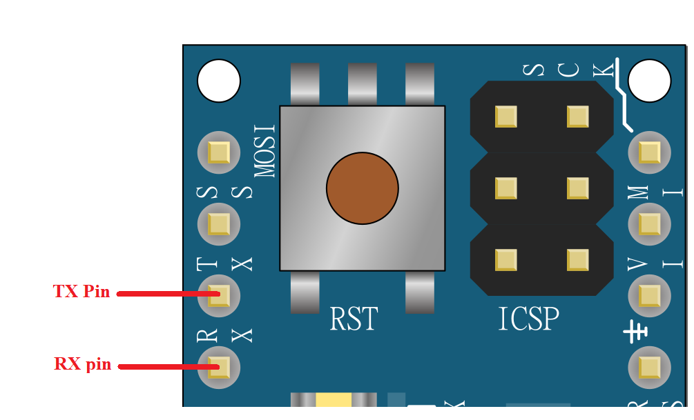
Arduino Micro TX and RX pins
UART pins are used for serial communication. 0 (RX) to receive the data, and 1 (TX) to transmit (TX) TTL serial data using the ATmega32U4 hardware serial capability.
ICSP pins on Arduino Micro:
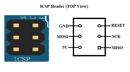
Arduino Micro ICSP Header
- ICSP stands for In-Circuit Serial Programming.
- The header pins of ICSP are used to program the firmware of the Arduino Micro board.
- The new firmware upgrades with the new capabilities are sent in through the microcontroller with the help of this ICSP header.
- The ICSP header consists of 6 pins.
Two-Wire Interface (TWI)/I2C pins:
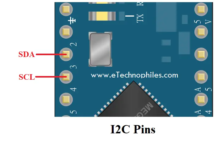
I2C Pins on Arduino Micro
I2C is the two-wire serial communication protocol. The I2C protocol stands for Inter-Integrated Circuits. It uses two pins for sending and receiving data: a serial clock (SCL) pin and a serial data (SDA) pin.
- SCL-It stands for Serial Clock. It is defined as the pin that transmits the clock data between the devices. It is used for synchronization purposes; the Serial Clock is provided by the master device.
- SDA-It stands for Serial Data. This pin is used by both the slave and master device to send and receive the data in between. That’s why it is also called a data line, while SCL can be called a clock line.
External Interrupt pins on Arduino Micro:

Interrupt pins on Arduino Micro
- There are 4 external interrupts pins on the Arduino Micro board: 3 (INT 0) , 2 (INT 2) , 0 (INT 3) and, 1 (INT 4) .
- The interrupts pins can be configured to trigger the interrupt if any of the following changes occur: a low value, a rising or falling edge, or a change in value.
SPI Pins on Arduino Micro board:
- It stands for Serial Peripheral Interface.
- These pins are used by the microcontrollers to communicate with one or more peripheral devices efficiently.
- Unlike Arduino UNO, the SPI pins of the Micro board are present on the ICSP header , these pins support SPI communication using the SPI library.
- This means that even if we have an external shield that uses SPI protocol but does NOT consist of a 6-pin ICSP connector that can bridge with the Arduino Micro’s 6-pin ICSP header, the shield will not work.
Other Pins on the Arduino Micro board:
AREF pin: Reference voltage for the analog inputs. Used with the function analogReference().
RESET pin: When 0volts / Low is given to this pin, it resets the board.
Specifications of Arduino Micro:
| Microcontroller | ATmega32U4 |
| Operating Voltage | 5V |
| Input Voltage (recommended) | 7-9V |
| Input Voltage (limit) | 6-9V |
| Digital I/O Pins | 20 |
| PWM Channels | 7 |
| Analog Input Channels | 12 |
| DC Current per I/O Pin | 20 mA |
| DC Current for 3.3V Pin | 50 mA |
| Flash Memory | 32 KB (ATmega32U4) of which 4 KB is reserved for the bootloader |
| SRAM | 2.5 KB (ATmega32U4) |
| EEPROM | 1 KB (ATmega32U4) |
| Clock Speed | 16 MHz |
| LED_BUILTIN | 13 |
| Length | 48 mm |
| Width | 18 mm |
| Weight | 13 g |
Arduino Micro Schematic :
**To download Arduino Micro schematic in PDF format, click here.
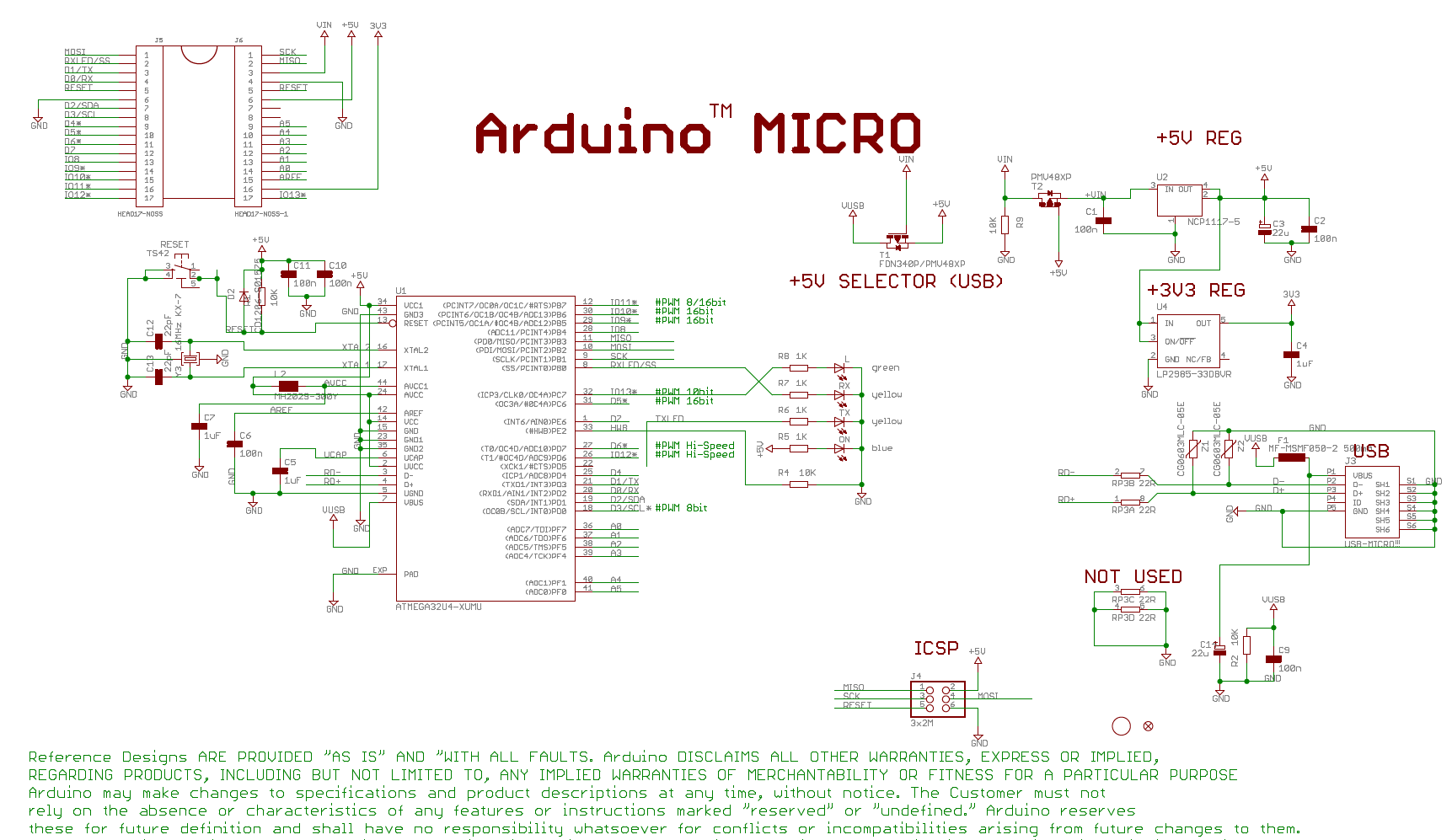
Arduino Micro schematic
Atmega32U4 Datasheet:
To download the datasheet of the Atmega328UA microcontroller chip, click here.
Arduino Micro Dimensions/ board size :
The board size of Arduino micro is 1.9″ x 0.7″ OR 48mm x 18mm.
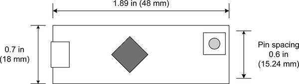
Arduino Micro dimensions
1 thought on “Arduino Micro Pinout, Specifications, Schematic datasheet”
I’m missing the little dot rotation indicator at the ICSP/SPI pins picture. The orientation is 180 degrees different from the one in the ArduinoISP example patch, which caused some confusion with me(a beginner).
Leave a Comment Cancel reply
Источник: