


The AD9833 DDS Signal Generator And Arduino Uno GPL3+
Содержание
Generate Square waves, Triangle Waves and Sine waves at any frequency between 0.1 Hz and 12.5 MHz using your Arduino and this amazing chip.
- 527 views
- 1 comment
- 1 respect
Components and supplies
Necessary tools and machines
About this project
The AD9833 is a Direct Digital Synthesizer that can generate a sine wave, square wave or triangle wave between 0.1 Hz and 12.5 Mhz with a resolution of 0.1 Hz. It is easy to connect up and control using your Arduino Uno and an open source library.
In this article, I show you how to obtain a breakout board, the basic connection setup and a simple example sketch for the Arduino Uno.
Note: You will need an oscilloscope to properly examine the properties of this amazing chip and view the wave forms it generates.
Obtaining An AD9833 DDS Generator Breakout Board
Since the AD9833 is a surface mount chip, the easiest way to experiment with it is to get yourself a breakout board. These can be purchased from Ebay, or Ali Express for less than $10. The particular board I bought seems to be the most popular and versatile (but there are many different versions) and it is shown in the image below. This is the board I will be using in this tutorial, but other boards will probably work just as well.
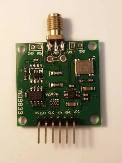 AD9833 Breakout Board. Approximate cost: $8-$10. Source: Ebay
The pin connections at the bottom of the board are the SPI interface connection pins and power pins that connect to your Arduino. The SPI interface is used to select the waveform and frequency.

The PGA and VOUT connections at the top of the board are the signal output connections. The PGA connection is an amplified copy (approximately 3 volts) of the 600 millivolt signal generated by the chip that appears at VOUT. The board contains an opamp that amplifies the 600 millivolt signal output of the chip and provides that output on the PGA connection. We’ll be using the amplified PGA output connection in this tutorial to view the output wave form on an oscilloscope.
Connecting The AD9833 Breakout Board
To connect up the AD9833 to your Arduino Uno make the following connections between the Arduino Uno and the breakout board:
DAT — Arduino Pin 11 // SPI Data pin
CLK — Arduino Pin 13 // SPI Clock pin
FSY — Arduino Pin 10 // SPI Load pin (FSYNC in AD9833 terminology)
Also, make the following connection for the chip select:
CS — Arduino Pin 9 // chip select for MCP41010
Make sure you also connect up the board’s VCC and GND connections to your Arduino’s power pins. To ensure a clean signal, I also recommend that you connect a 10uF capacitor between VCC and GND.
Before you can run the example sketch, you will need a 3rd party library that simplifies communication between your code and the AD9833. To obtain this library visit the following GitHub repository , download the ZIP archive file and extract its contents into your Arduino IDE’s sketchbook/libraries folder. Then, restart your Arduino IDE to make it visible.
The example sketch below generates a 1 MHz square wave signal. Create a new project for it in your Arduino IDE and compile and upload it to the Arduino Uno.
Connect your oscilloscope probe to the PGA connection on the board and view the waveform. That’s it. Have fun experimenting with different waveforms.
Источник: