


ESP8266 Pinout Overview [ESP-01, NodeMCU, WeMos D1 Mini]
Содержание
The following article give you an overview of the ESP8266 pinout of different boards I use.
We compare the specifications of the different microcontroller and take a look at the pinout in detail.
Also you find an overview of different possibilities of power supply.

Table of Contents
If you want detailed technical specifications about the ESP8266 I wrote this article where I compared the technical specifications from different Arduino, ESP8266 and ESP32 microcontroller.
The following table gives you an overview of all components and parts that I used for this tutorial. I get commissions for purchases made through links in this table.
| Component | Amazon Link | AliExpress Link |
|---|---|---|
| ESP8266 ESP-01 | Amazon | AliExpress |
| ESP8266 NodeMCU | Amazon | AliExpress |
| ESP8266 WeMos D1 Mini | Amazon | AliExpress |
ESP-01
The ESP-01 is a very small module based on the ESP8266 microcontroller. The ESP-01 measures 25 mm by 14 mm and has 8 GPIOs. Like all modules based on the ESP8266 it has WiFi included. There are a 1MB flash and a 512 kB flash version available.
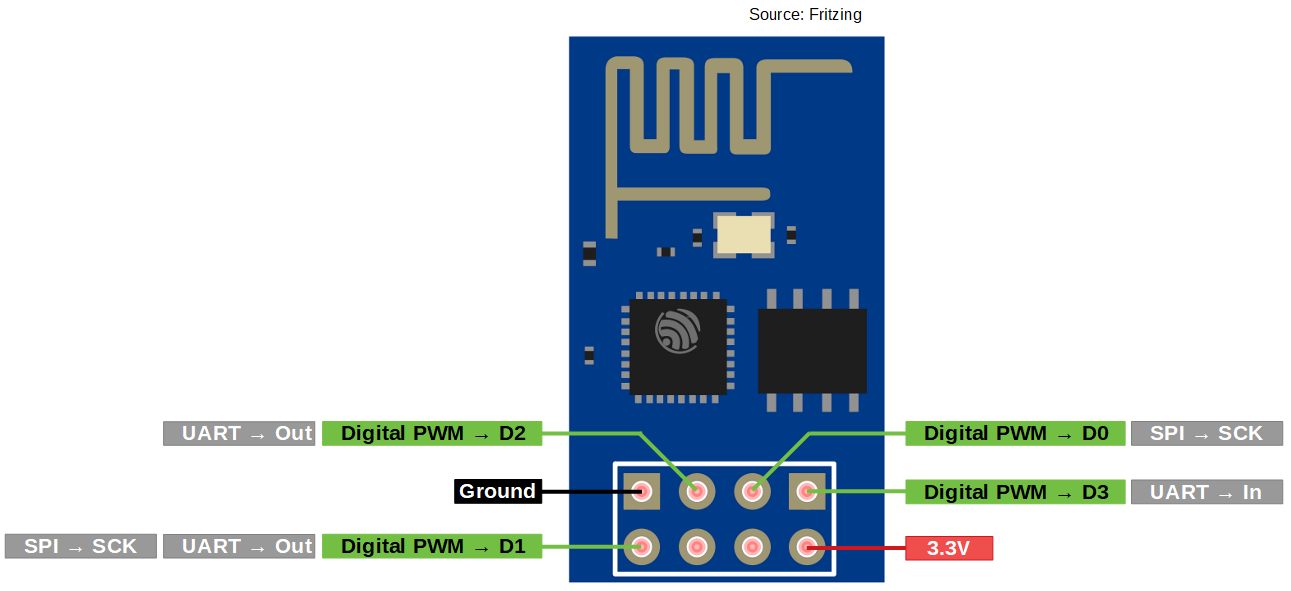
ESP8266 Pinout of ESP-01
| Module Pin | Arduino Pin | Name | Description |
|---|---|---|---|
| 1 | 3 | RxD (GPIO3) | Serial input or normal I/O Pin |
| 2 | VCC | Power supply 3.3V, 400mA | |
| 3 | 0 | GPIO0 | Low at boot activates firmware upload, must be not connected or high at normal start |
| 4 | RESET | Low = Reset, has weak pull-up resistance to high | |
| 5 | 2 | GPIO2 | Flickers at the start, may not be pulled low at the start |
| 6 | ENABLE | Must be pulled high for the chip to work. Low = Power Down, High = Enabled | |
| 7 | GND | Ground | |
| 8 | 1 | TxD (GPIO1) | Serial output or normal I/O pin, is connected to the blue LED, flickers at startup, must not be pulled low at startup |
ESP-01 Power Supply
Microcontroller Datasheet eBook
The 35 pages Microcontroller Datasheet Playbook contains the most useful information of 14 Arduino, ESP8266 and ESP32 microcontroller boards.
ESP8266E-12 (NodeMCU)
The NodeMCU board got his name from an open source IoT platform. The platform includes firmware which runs on the ESP8266 WiFi SoC from Espressif Systems, and hardware which is based on the ESP-12 module. The NodeMCU incorporates 4MB flash memory. If you want to buy this board you will find it under the name NodeMCU or ESP8266E-12.
You will find different versions of the board.
- Version 1 is quite old and I would not recommend to use it for future projects.
- The V2 fixes the short comings of the initial board, it’s more narrow and fits nicely into bread boards. Also the chip was upgraded from a ESP-12 to a ESP-12E.
- The Version 3 is invented by producer LoLin with slightly minor improvements. They claim that their USB port is more robust. LoLin decided to use one of the two reserve pins for USB power out and the other for an additional ground. But the major downside of the V3 board is its size. The dimension of the V2 are 48x26x13 mm compared to the V3 with 58x31x13 mm. Therefore the V3 board will not fit on a breadboard.

My recommendation is to use the Version 2 because I like to test my prototypes on a breadboard and do not see the advantages using the Version 3.
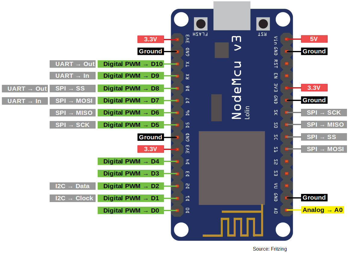
ESP8266 Pinout of NodeMCU
The NodeMCU has in total 4 different power pins:
- 3 pins provide 3.3V and 400mA
- 1 pin marked as VIN provides 5V and can power the whole NodeMCU between 7V-12V with up to 1A
and in total 5 ground pins to close the electric circuit.
The ESP8266 has a lot of communication pins:
Some of the communication pins can also be used as digital input/output pins.
The NodeMCU has in total 10 digital I/O pins which are all PWM ready.
Unfortunately the NodeMCU has only 1 analog pin which has a voltage range of 0V-3.2V and is connected to a voltage divider composed of two resistances 220kΩ and 100kΩ.
NodeMCU Power Supply
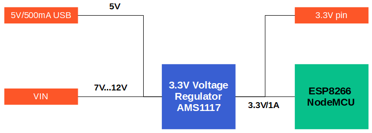
You have 3 possibilities for a power supply of the NodeMCU:
- Operate the NodeMCU on the 3.3V input with 2.5V to 3.6V
- Operate the NodeMCU on the VIN input pin with a voltage between 7V and 12V
- Use a USB cable with 5V. A diode prevents current from the 5V input to the USB connection flows.
The built-in voltage regulator has a maximum power reserve of 300mA for external expansions at 5V input voltage.
WeMos D1 Mini
The WeMos D1 Mini with integrated ESP8266 has an operating voltage of 3.3V and 4MB flash memory. Its size 34.2mmx25.6mm is between the NodeMCU and ESP-01 module by Ai-Thinker.
There are different versions of the WeMos D1 Mini board
| Version | ESP Chip | Flash Memory | LED Pin | Antenna | Charge Controller |
|---|---|---|---|---|---|
| Wemos D1 Mini Lite v1 | ESP8285 | 1 MB | yes | conductor loop | no |
| Wemos D1 Mini v2 | ESP8266 | 4 MB | no | conductor loop | no |
| Wemos D1 Mini v3 | ESP8266 | 4 MB | yes | conductor loop | no |
| Wemos D1 Mini Pro v1 | ESP8266 | 16 MB | yes | Ceramic antenna and ext. antenna connection | no |
| Wemos D1 Mini Pro v2 | ESP8266 | 16 MB | yes | Ceramic antenna and ext. antenna connection | yes |
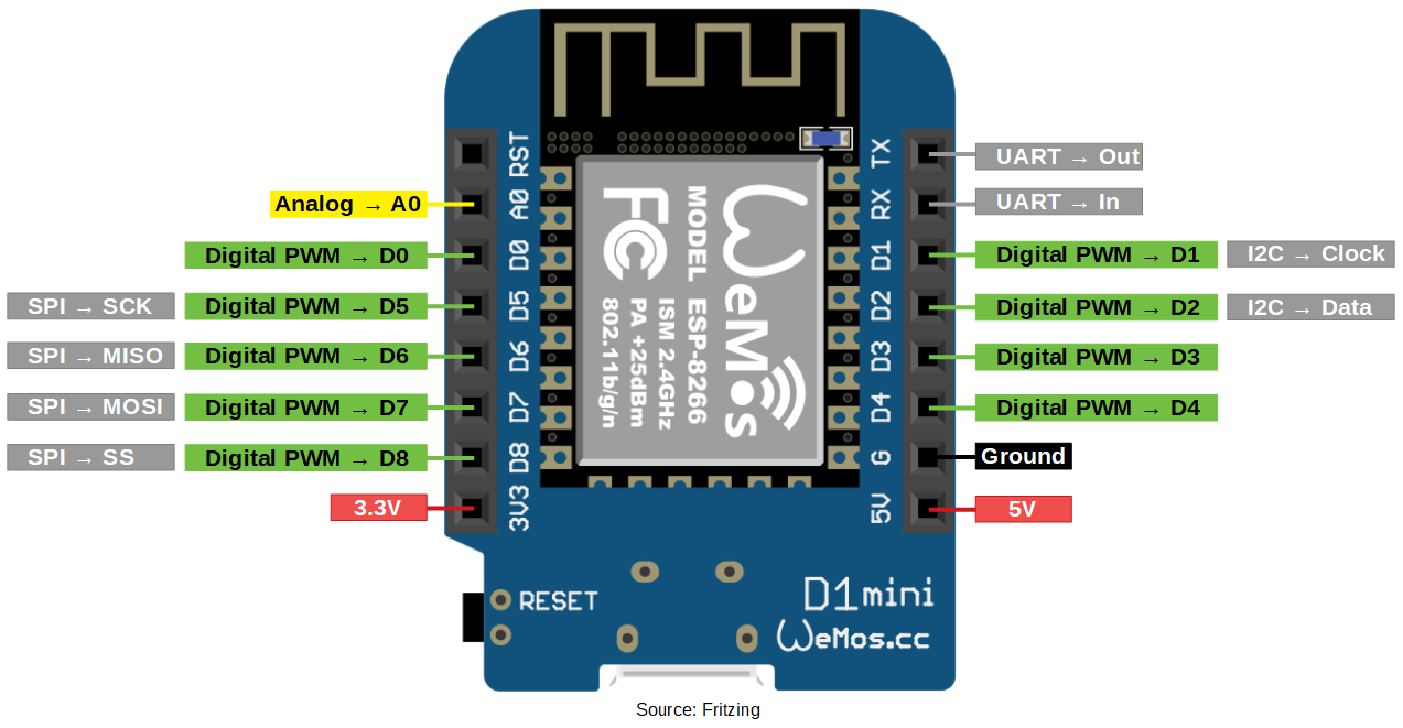
ESP8266 Pinout of WeMos D1 Mini
Because the WeMos D1 Mini is also based also on the ESP8266, the possible pinout would be the same as the NodeMCU. But the WeMos D1 Mini is more like a litte version of the NodeMCU with fewer pins but still enough for basic projects.
The WeMos D1 Mini has a 3.3V and 5V output to power different external components. Both pins can provide up to 500mA and the 5V pin is also able to power the whole board with a supply voltage between 4V-6V. The circuit is closed over one ground pin.
Instead of 10 digital I/O pins, the WeMos has only 8 digital I/O pins, which are also all able to produce a PWM signal.
The WeMos has also all communication pins:
Because the ESP8266 has only 1 analog pin, the WeMos D1 Mini has also this 1 analog pin.
Источник: