


Vin arduino
Looking at the board from the top down, this is an outline of what you will see (parts of the board you might interact with in the course of normal use are highlighted):
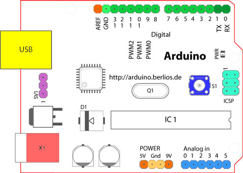
Starting clockwise from the top center:
- Analog Reference pin (orange)
- Digital Ground (light green)
- Digital Pins 2-13 (green)
- Digital Pins 0-1/Serial In/Out — TX/RX (dark green) — These pins cannot be used for digital i/o (digitalRead and digitalWrite) if you are also using serial communication (e.g. Serial.begin).
- Reset Button — S1 (dark blue)
- In-circuit Serial Programmer (blue-green)
- Analog In Pins 0-5 (light blue)
- Power and Ground Pins (power: orange, grounds: light orange)
- External Power Supply In (9-12VDC) — X1 (pink)
- Toggles External Power and USB Power (place jumper on two pins closest to desired supply) — SV1 (purple)
- USB (used for uploading sketches to the board and for serial communication between the board and the computer; can be used to power the board) (yellow)
Microcontrollers
ATmega328P (used on most recent boards)
| Digital I/O Pins | 14 (of which 6 provide PWM output) |
| Analog Input Pins | 6 (DIP) or 8 (SMD) |
| DC Current per I/O Pin | 40 mA |
| Flash Memory | 32 KB |
| SRAM | 2 KB |
| EEPROM | 1KB |
ATmega168 (used on most Arduino Diecimila and early Duemilanove)
| Digital I/O Pins | 14 (of which 6 provide PWM output) |
| Analog Input Pins | 6 (DIP) or 8 (SMD) |
| DC Current per I/O Pin | 40 mA |
| Flash Memory | 16 KB |
| SRAM | 1 KB |
| EEPROM | 512 bytes |
ATmega8 (used on some older board)

| Digital I/O Pins | 14 (of which 3 provide PWM output) |
| Analog Input Pins | 6 |
| DC Current per I/O Pin | 40 mA |
| Flash Memory | 8 KB |
| SRAM | 1 KB |
| EEPROM | 512 bytes |
Digital Pins
In addition to the specific functions listed below, the digital pins on an Arduino board can be used for general purpose input and output via the pinMode(), digitalRead(), and digitalWrite() commands. Each pin has an internal pull-up resistor which can be turned on and off using digitalWrite() (w/ a value of HIGH or LOW, respectively) when the pin is configured as an input. The maximum current per pin is 40 mA.
-
Serial: 0 (RX) and 1 (TX). Used to receive (RX) and transmit (TX) TTL serial data. On the Arduino Diecimila, these pins are connected to the corresponding pins of the FTDI USB-to-TTL Serial chip. On the Arduino BT, they are connected to the corresponding pins of the WT11 Bluetooth module. On the Arduino Mini and LilyPad Arduino, they are intended for use with an external TTL serial module (e.g. the Mini-USB Adapter).
Analog Pins
In addition to the specific functions listed below, the analog input pins support 10-bit analog-to-digital conversion (ADC) using the analogRead() function. Most of the analog inputs can also be used as digital pins: analog input 0 as digital pin 14 through analog input 5 as digital pin 19. Analog inputs 6 and 7 (present on the Mini and BT) cannot be used as digital pins.
- I 2 C: 4 (SDA) and 5 (SCL). Support I 2 C (TWI) communication using the Wire library (documentation on the Wiring website).
Power Pins
- VIN (sometimes labelled "9V"). The input voltage to the Arduino board when it’s using an external power source (as opposed to 5 volts from the USB connection or other regulated power source). You can supply voltage through this pin, or, if supplying voltage via the power jack, access it through this pin. Note that different boards accept different input voltages ranges, please see the documentation for your board. Also note that the LilyPad has no VIN pin and accepts only a regulated input.
Other Pins
- AREF. Reference voltage for the analog inputs. Used with analogReference().
Corrections, suggestions, and new documentation should be posted to the Forum.
The text of the Arduino reference is licensed under a Creative Commons Attribution-ShareAlike 3.0 License. Code samples in the reference are released into the public domain.
Источник: