


Using CCM on STM32F303CC
There are many silicon vendors that make MCUs and most of them they use the same cores (e.g. ARM Cortex). Therefore, in order to compete each other, vendors need to make themselves stand out from their competitors and this is done in many different ways. Of course, the most important is the price, but some times that’s not enough, because even the low price doesn’t mean that the controller fits your project. Therefore, vendors come with different peripherals, clocks, power saving modes e.t.c.
Sometimes though, vendors provide some very interesting features in their cores and in this post I will get down to the Core-Coupled Memory (CCM) that you can find in some STM32 MCUs. In this post I’ll use the STM32F303CC, as I’ve already have written a cmake template project for this here that I use for fast development and testing.
Components
As I’ve said in this post I’ll use the STM32F303CC and specifically I’ll use the RobotDyn STM32-MINI (or black-pill) module. Well, don’t get confused, there are many different black-pill modules (some with an STM32F411, which I’ll use on a future stupid project). The one I’m using is this:
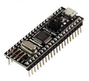
This beauty has 256KB flash, 40KB SRAM and 8KB of CCM RAM.
What is CCM?
The STM32F303 reference manual refers to the CCM as:
You can get a better explanation though in the application note AN4296. I’ll just copy part of the appnote here.
The CCM SRAM is tightly coupled with the Arm® Cortex® core, to execute the code at the maximum system clock frequency without any wait-state penalty. This also brings a significant decrease of the critical task execution time, compared to code execution from Flash memory. The CCM SRAM is typically used for real-time and computation intensive routines, like the following:
- digital power conversion control loops (switch-mode power supplies, lighting)
- field-oriented 3-phase motor control
- real-time DSP (digital signal processing) tasks
When the code is located in CCM SRAM and data stored in the regular SRAM, the Cortex-M4 core is in the optimum Harvard configuration . A dedicated zero-wait-state memory is connected to each of its I-bus and D-bus (see the figures below) and can thus perform at 1.25 DMIPS/MHz, with a deterministic performance of 90 DMIPS in STM32F3 and 213 DMIPS in STM32G4. This also guarantees a minimal latency if the interrupt service routines are placed in the CCM SRAM.
The architecture of the CCM RAM is the following one:
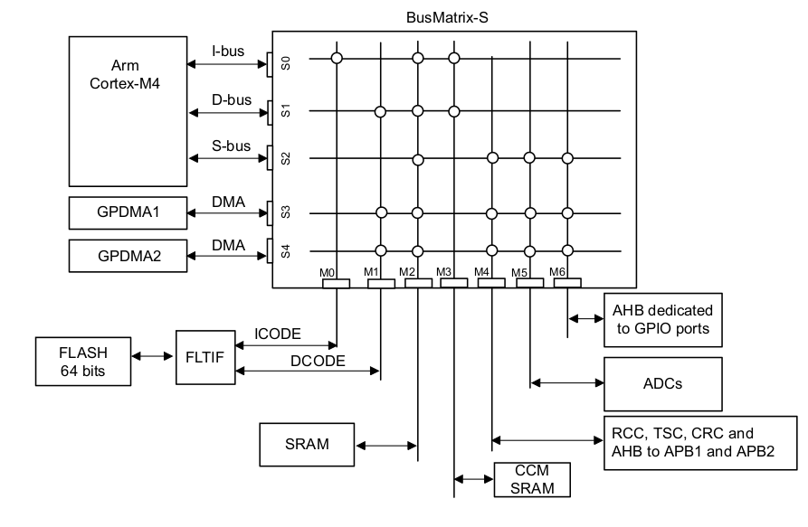
As you can see the CCM SRAM is connected only to the i-bus (S0 — M3) and D-bus (S1 — M3). Since there’s a zero-wait it means that it’s the fastest RAM you can use.
Show me the code!
So how to use it then? First you need to clone this cmake repo from here:
This is a cmake project based on this template here and it’s configured to enable the CCM RAM area. By default the CCM RAM is only enabled in the linker file which is the `source/config/LinkerScripts/STM32F303xC/STM32F303VC_FLASH.ld`, but I had also to edit the start up file `source/libs/cmsis/device/startup_stm32f30x.s` for actually be able to use the CCM RAM. In the start up file you’ll find this code here:
Also in the linker file you can see the memory area and it’s size which is that one:
As you can see the SRAM area starts at address 0x20000000 and it’s 40K and the CCMRAM starts at 0x10000000 and it’s 8K. It’s important to remember those addresses when debugging your code, because it will save you from a lot of time if you know what you’re looking for and what to expect.
In the linker file I’ve also added an .sram section in order to be able to map functions in the RAM. You can see this here:
The .sram and .sram* is the sections I’ve added my self. Also in the same file you can find the .ccmram section here:
In order to test the CCMRAM you need a reference code that it can stress your CPU and RAM and for that reason I’ve decided to use LZ4. LZ4 is a fast compression library which has a very small footprint, it’s written in pure C so it’s portable and it has a lot more benefits that for now are irrelevant. From this library I’ll only use one function for compression without decompression or verification as it doesn’t matter. Since I only care for testing the performance it means that evaluating the library functionality is not critical for the task.
The LZ4 library is located in `source/libs/lz4` and I’ve written a cmake module which is located in `source/cmake/lz4.cmake`. As you can see it’s only a header and C source file.
In the main.c file the interesting code is the block size and count used for the compression test routine. The block size is just the size of the buffer that the compression routine will process and the block count is actually the number of the blocks that will be processed. There is an enum that defines those numbers:
The USE_BLOCK_COUNT and USE_BLOCK_SIZE are defined in the build.sh script which passes those variables in the cmake. The default values are:
From the syntax probably you can see that these parameters can be overridden when running the script, therefore you can use any block size and block count. For example, for my tests I’ve used two different block sizes 8K and 6K and left the default block count. Therefore, the build script needs to be run like this:
As you can see I’ve used two different block sizes 8K and 16K and the count is 512. That means that the compression routine will process 512*1024*8 = 4MB of data and 8MB of data for each case. On the STM32F303CC there isn’t any 4MB or 8MB continuous storage, but I’m using USE_BLOCK_COUNT for this. You can see what I’ve done in the source code and specifically in the testing function in main.c.
As you can see from the above code I’m pointing with the inpPtr to the SRAM which begins in 0x2000000 then the code compresses the SRAM content using the given block size which is 8K and 16K. Remember the SRAM is 20K, therefore if you try with a block size bigger that 20K then the CPU will hang and it will end up looping in the MemManage_Handler() or HardFault_Handler() exception in the `source/src/stm32f30x_it.c`. That was actually a part of my tests, too in order to verify that is working as expected.
For many people that are having a background on embedded Linux, this might seem very strange, but for MCUs it’s fine to have access to all the range of the memory and read code. Some MCUs -including many STM32- have a memory protection unit (MPU) that disables write on defined memory areas. This most of the times is used to protect the stack from growing out of the limits, but it also has other usages.
Anyway, as you can also see in the previous code, the BLOCK_COUNT is actually a for loop that read the same SRAM area multiple times, therefore the 4MB and 8MB is not a sequential storage but it’s more like a “ring buffer” read in the SRAM.
Finally, the testing routine is called every 1 sec with this code here:
The glb_tmr_* are volatile variables that are incremented every 1ms in the SysTick_Handler() interrupt function in `source/src/stm32f30x_it.c`. As you can see from the function declaration I’ve used the .ccmram attribute in order to place the interrupt handler in the CCMRAM, so it executes faster.
Therefore, this is the magic line that you need to add to your functions in order to place them in the CCMRAM area:
The only thing that you need to make sure is that the function you want to place in CCMRAM it actually fits, but the linker will warn you anyways if it doesn’t.
The same way you can use another attribute to place code in the SRAM:
but I’ll get there later in a bit.
Last important thing is the `LZ4_compress_generic()` function that it’s called from the LZ4_compress_fast_continue() and does the actual compression and it’s located in the `source/libs/lz4/src/lz4.c` file. If you try to place the LZ4_compress_fast_continue() function in the CCMRAM this won’t work as it larger than 8K, but you also don’t have to as the `LZ4_compress_generic()` does the work.
The definition of the `LZ4_compress_generic()` function in the original source code here is this one:
Do you see this `LZ4_FORCE_INLINE`? We don’t like that. Why? Because inline functions cannot be moved to the CCMRAM or the SRAM! If you just use the following code it won’t work:
Instead you can see from the change I’ve made in `source/libs/lz4/src/lz4.c` that in order to be able to move the function to the CCMRAM you need to do this:
As you can see the USE_CCM flag controls if the function is placed in the .ccmram area. The USE_FLASH controls if it’s placed in the flash but inlined, which is a custom optimization that forces the inlining of this critical function. Finally the USE_SRAM flag places the function into the SRAM. Have in mind that if all flags are disabled, then the behavior is again to place the code in flash, but not inlined in the calling function. That means that the function will have it’s own address in the flash.
Exciting, isn’t it? OK, so before go to the benchmarks, let’s verify that those USE_* flags are actually working and what is the result. We can verify this in several ways. One is to print the function address in the firmware, which means that we need to build the firmware and then flash it on the targer. But there’s a better and more proper way to do this. In Linux you can just use the elfread tool and see the address of any function.
Verifying the build flags and memory areas
Before I proceed with the verification, I’ll list here the memory areas of the STM32F303CC.
| Memory | Start | Stop | Size (KB) |
| FLASH | 0x0800 0000 | 0x0803 FFFF | 256 |
| SRAM | 0x2000 0000 | 0x2000 9FFF | 40 |
| CCMRAM | 0x1000 0000 | 0x1000 1FFF | 8 |
Now, let’s first build the code with this command:
You don’t really need to write all the flags since they do have default values, but I’m doing this here for clarity. This will build the code and create an elf, hex and bin file in the `build-stm32/src/` folder. Now you can use this command to get the LZ4_compress_generic address:

This will return the following output:
From this response you can see that the function is located in 0x0800 158d, which means it’s located in the flash area. That means that the function is not inline but a proper calling function.
Now let’s build with this command here:
Again, use readelf to get the function address
Hmm, it prints nothing! What’s going on? Is that’s correct? Yes! Why? Because USE_FLASH=ON means that the function is inlined in the `LZ4_compress_fast_continue()` function, therefore you need to run this command:
which will print something similar to this:
Which means that this function is in the flash area (0x800015b1) and the LZ4_compress_generic() function is inlined in that function. This is why you don’t get an address for the LZ4_compress_generic() . Does it make sense now? OK, let’s see the next example, now try this command to build the firmware:
Now check again the elf:
This will print:
Now you see that the function address is located in 0x2000 00ed, therefore it’s located in the SRAM. That means that the flag works properly.
Now, test with this command:
Now check the elf file again:
This will print:
Now you see that the function is placed in the CCMRAM in 0x10000029. So, it works!
Some of you may wonder what’s this `__LZ4_compress_generic_ve` function that is printed when the function is placed in the SRAM or CCMRAM and why this function has an address in the flash? Well, that’s quite easy to answer. The only non-volatile storage on the MCU is the flash. SRAM and CCMRAM are volatile, which means that when the power is removed then all data are gone. Then if that’s the case, how this code works when you supply the MCU with power? How the function ends up in the SRAM and CCMRAM. Well, this is what the startup code does. Takes the address of those functions that are needed to be in the RAM and then copies the code in there. All the addresses are static, so the startup code just copies from and to pre-defined addresses. These addresses are set by the linker when you build the firmware as the linker knows exactly what memory is available.
Compilers and linkers are really interesting things, but I won’t spend more time on them now. Also, I’m not an expert on the subject (not even close). Therefore, I hope that at least it’s clear how the things are put together so far and how this functions are places from flash into different memory areas.
Build command
Before continue with the benchmarks, let’s have a look in the build command. The syntax format is the following.
And this is the explanation of all the flags:
- `USE_OVERCLOCKING`, ON: enable overclocking at 128MHz, OFF: 72MHz
- `USE_BLOCK_SIZE`, number of bytes used as the block size. Default: 8, which means 8K
- `USE_BLOCK_COUNT`, number of blocks used for the compression. Default: 512.
- `USE_CCM`, ON: move compression function to CCMRAM
- `USE_SRAM`, ON: move compression function to SRAM
- `USE_FLASH`, ON: move compression function to FLASH
These are some notes for the parameters:
- Only one of the `USE_CCM`, `USE_SRAM`, `USE_FLASH` can be `ON`.
- The processed size will be `USE_BLOCK_SIZE`*`USE_BLOCK_COUNT`
- The default processed size is 4MB
- The `USE_BLOCK_SIZE` can not be larger than 20KB
As I’ve mentioned all the parameters have already default value, therefore you don’t have to write those long commands. You can change the default values in the build.sh script instead.
Using Docker
Instead of setting up a build environment, then if you have docker you can use my CDE image to build the code without much hassle. Just clone the code like this:
And then to build the CCM example, run this command:
You can use any of the build commands I’ll mention in the next section by just placing them in the double quotes after the -c in the docker command.
Benchmarks
Some benchmarks at last! Well, that’s always my favorite part and it always takes some time to get here as it wouldn’t be beneficial for others if I didn’t explain how I get to this point. So, now that we verified that the flags are working, it’s time to start benchmarking. To make it even better I’ll benchmark the compression code in the maximum MCU core default frequency which is 72MHz and when its overclocked at 128MHz.
To do this I’ve build the code with various flag combinations, then flash it on the target and then wait for the UART output to get the time in msec. I’ve also used a GPIO that tooggles to verify that the time is printed is valid and I can say for sure that it is. Therefore, this is the list of the commands I’ve used.
Flash benchmarks (non-inline function)
FLASH benchmarks (inline function)
SRAM benchmarks
CCMRAM benchmarks
Finally, this is a table with all the results. The table shows the execution time of the test_lz4() function and all numbers are in milliseconds. Therefore, the smaller the number the faster was the execution.
| FLASH (non-inline) |
FLASH (inline) |
SRAM | CCMRAM | |
| 8K @72MHz | 279 | 304 | 251 | 172 |
| 8K @128MHz | 156 | 171 | 141 | 97 |
| 16K @72MHz | 466 | 631 | 496 | 340 |
| 16K @128MHz | 262 | 355 | 278 | 191 |
There are so many interesting things in this table!
- It’s clear who’s the winner. CCM is faster compared to any other memory.
- SRAM doesn’t seem much faster compared to Flash, can you see this?
- By forcing the inline to the compiler ( LZ4_FORCE_INLINE ) actually makes things worse for both block sizes! The compiler optimizations do better job, but on the other hand the inline is forced by the library itself. Therefore, you need to actually remove it to gain more performance! Awesome finding.
- When the block size is 16K, the FLASH code is faster than the SRAM!
OK, so now let’s see how much faster the CCMRAM is in this case.
| CCMRAM | FLASH (non-inline) |
FLASH (inline) |
SRAM |
| 8K @72MHz | 47.45% | 55.46% | 37.35% |
| 8K @128MHz | 46.64% | 55.22% | 36.97% |
| 16K @72MHz | 31.26% | 59.93% | 37.32% |
| 16K @128MHz | 31.34% | 60.07% | 37.1% |
As you can see from this table the CCM RAM is faster from 31% up to 60% and that’s a huge gain! Therefore, CCM is as advertised the fastest RAM that you can use on the STM32F303CC. It’s only shame that it’s only 8K 🙁
Conclusion
This stupid project was really fun. I’ve spotted by chance this CCM RAM in the datasheet and I thought, meh, let’s try it. I was expecting that it would be a bit faster, but I didn’t expect that the difference would be that great. 31% faster is a lot of performance gain, you can’t ignore this, especially in time critical code.
To be honest, I didn’t expect that the flash would be faster than the RAM, but I have a theory for this. My theory is that this happens because I’m using the RAM as an input to the compression function and when the block size is 16KB -which is almost all the RAM- then it seems that this slows down the R/W. It seems that in this case the CPU performs better when executing less code from the RAM. That’s my theory, but it doesn’t mean that it’s right. But in any case, with large blocks the STM32 performs better if the function is executed from the flash.
Finally, the LZ4_FORCE_INLINE in the LZ4_compress_generic() it seems that makes performance worse and the GCC compiler with the compiler and linker flags I’ve used makes better job.
After this, I’ve also updated my cmake template for the STM32F303CC, so I’m able to use the __attribute__ directive for both .ccmram and .sram areas and place functions in there.
Источник: