


Programming STM32 Based Boards with the Arduino IDE

Since it’s inception the Arduino IDE has demonstrated the desire to support all kind of platforms, from Arduino clones and variations of different manufacturers to third party boards like the ESP32 and ESp8266. As more people get familiar with the IDE, they are beginning to support more boards that are not based on ATMEL chips and for today’s tutorial we will look on one of such boards. We will examine how to program the STM32 based, STM32F103C8T6 development board with the Arduino IDE.
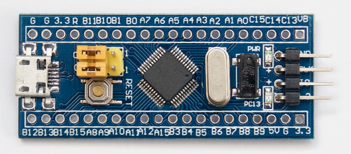

The STM32 board to be used for this tutorial is none other than the STM32F103C8T6 chip based STM32F1 development board commonly referred to as “Blue Pill” in line with the blue color of its PCB. Blue Pill is powered by the powerful 32-bit STM32F103C8T6 ARM processor, clocked at 72MHz. The board operates on 3.3v logic levels but its GPIO pins have been tested to be 5v tolerant. While it does not come with WiFi or Bluetooth like the ESP32 and Arduino variants, it offers 20KB of RAM and 64KB of flash memory which makes it adequate for large projects. It also possesses 37 GPIO pins, 10 of which can be used for Analog sensors since they have ADC enabled, along with others which are enabled for SPI, I2C, CAN, UART, and DMA. For a board which costs around $3, you will agree with me that these are impressive specs. A summarized version of these specifications compared with that of an Arduino Uno is shown in the image below.
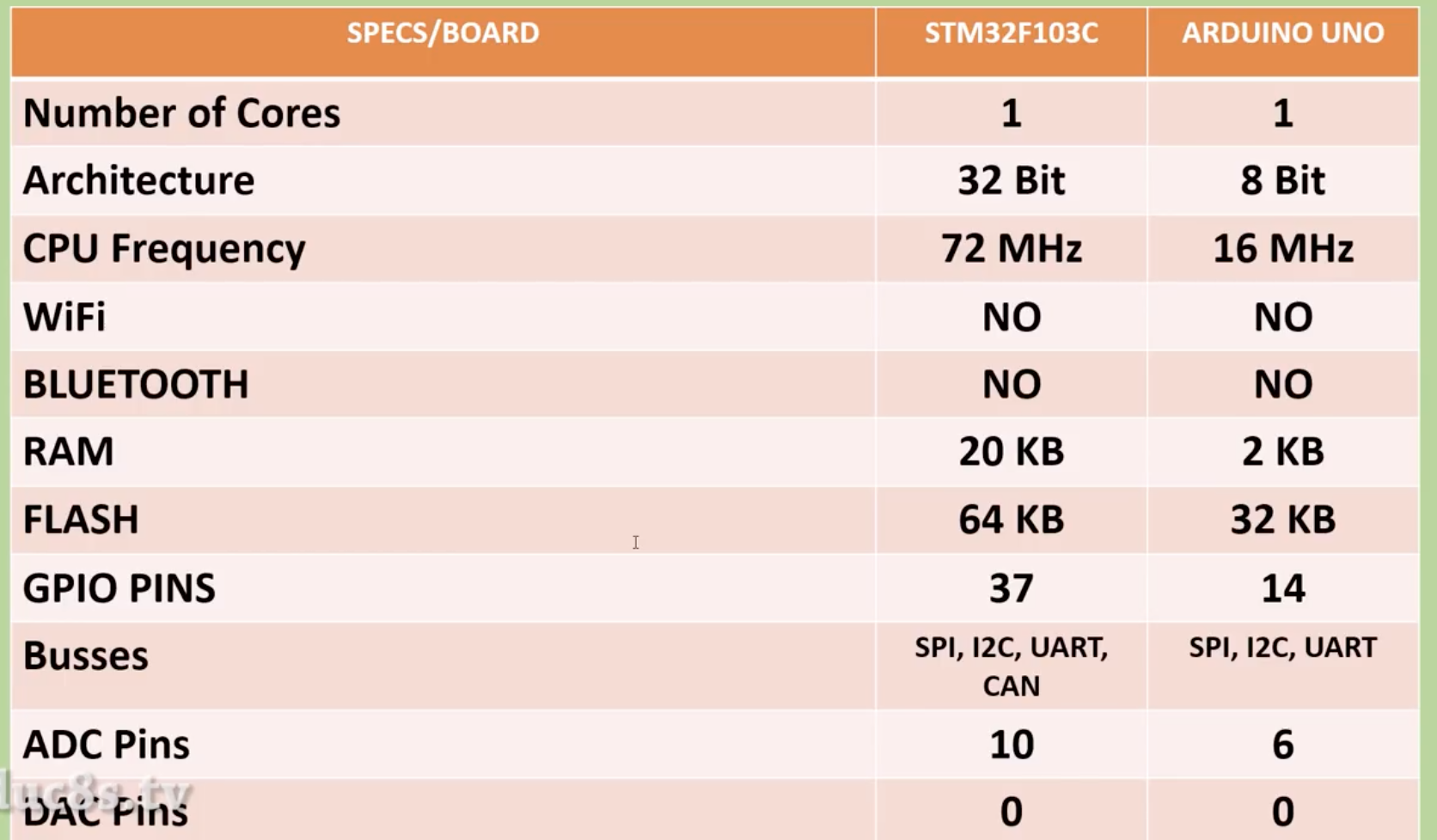
Based on the specs above, the frequency at which Blue pill operates is about 4.5 times higher than an Arduino UNO, for today’s tutorial, as an example on how to use the STM32F1 board, we will connect it to a 1.44″ TFT display and program it to calculate the “Pi” constant. We will note how long it took the board to obtain the value an compare it with the time it takes an Arduino Uno to perform the same task.
Required Components
The following components are required to build this project;
As usual, all the components used for this tutorial can be bought from the attached links. The power bank is however only needed if you want to deploy the project in a stand-alone mode.
Schematics
As mentioned earlier, we will connect the STM32F1 board to the 1.8″ ST7735 based colored TFT Display along with a push button. The push button will be used to instruct the board to start the calculation.
Connect the components as shown in the Schematics below.
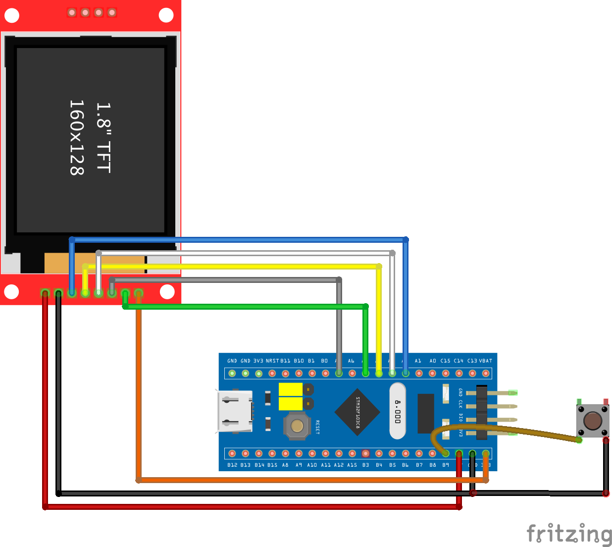
To make the connections easy to replicate, the pin to pin connections between the STM32 and the display is described below.
STM32 ST7735
Go over the connections once again to be sure everything is as it should be as it tends to get a little bit tricky. With this done, we proceed to set up the STM32 board to be programmed with the Arduino IDE.
Setting up the Arduino IDE for STM32
As with most boards not made by Arduino, a bit of setup needs to be done before the board can be used with the Arduino IDE. This involves installing the board file either via the Arduino Board manager or downloading from the internet and copy the files into the hardware folder. The Board Manager route is the less tedious one and since the STM32F1 is among the listed boards, we will go that route.
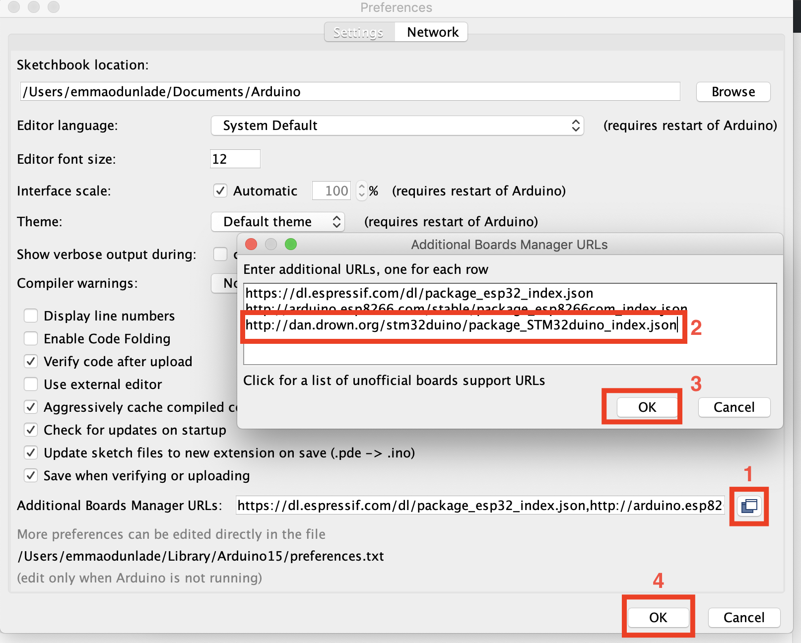
Start by adding the link for the STM32 board to the Arduino preference lists. Go to File — Preferences, then enter this URL ( http://dan.drown.org/stm32duino/package_STM32duino_index.json ) in the box as indicated below and click ok.
Now go to Tools — Board — Board manager, it will open a dialogue box with a search bar. Search for STM32F1 and install the corresponding package.
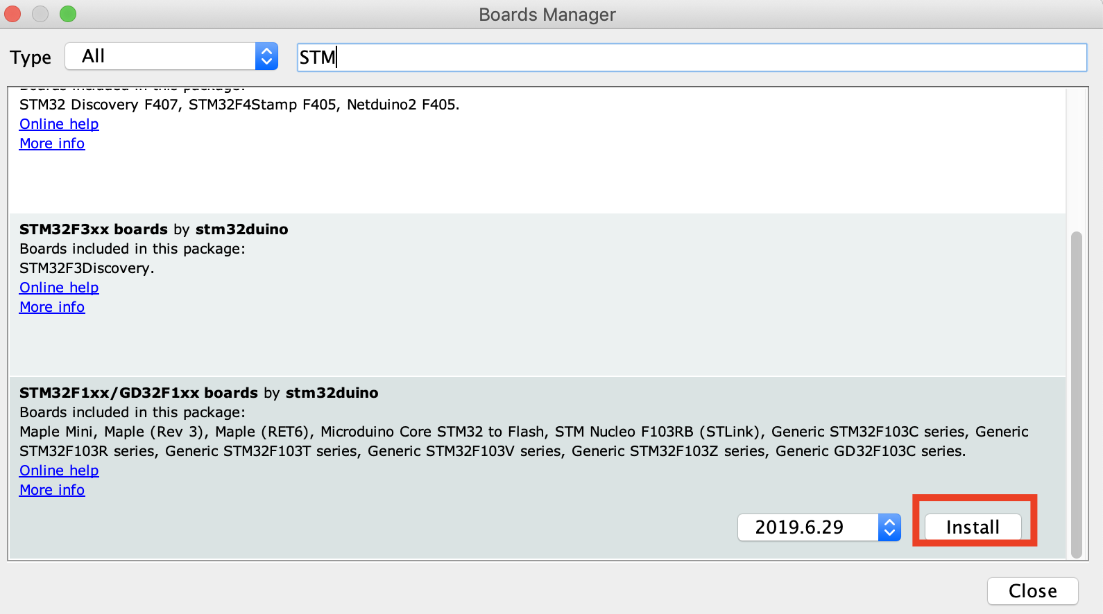
The installation procedure will take a few seconds. After that, the board should now be available for selection under the Arduino IDE board list.
The code will be written the same way we’d write any other sketch for an Arduino project, with the only difference being the way the pins are referenced.
To be able to easily develop the code for this project, we will use two libraries which are both modifications of standard Arduino Libraries to make them compatible for the STM32. We will use the modified version of the Adafruit GFX and the Adafruit ST7735 libraries. Both libraries can be downloaded via the links attached to them.

As usual, I will be doing a short breakdown of the code. We start the code by importing the two libraries that we will use.
Next, we define the pins of the STM32 to which the CS, RST, and DC pins of the LCD are connected.
Next, we create some color definitions to make it easy to use colors by their names in the code later instead of by their hex values.
Next, we set the number of iterations we want the board to go through along with the refresh duration for the progress bar to be used.
With this done, we create an object of the ST7735 library which will be used to reference the display all through the entire project. We also indicate the pin of the STM32 to which the pushbutton is connected and create a variable to hold its state.
With this done, we move to the void setup() function.
We start by setting the pinMode() of the pin to which the pushbutton is connected, activating an internal pull-up resistor on the pin since the pushbutton connects to ground when pressed.
Next, we initialize serial communication and the screen, setting the background of the display to black and calling the printUI() function to display the interface.
Next is the void loop() function.
The void loop function is quite simple and short, thanks to the use of libraries/functions.
We start by reading the state of the push button. If the button has been pressed, we remove the current message on the screen using the removePressKeyText() and draw the changing progress bar using the drawBar() function. We then call the start calculation function to obtain and display the value of Pi along with the time it took to calculate it.
If the pushbutton is not pressed, the device stays in Idle mode with the screen demanding that a key be pressed to interact with it.
Finally, a delay is inserted at the end of the loop to give a bit of time before sketch “loops”.
The remaining part of the code are the functions called to achieve the tasks from drawing the bar to calculating the Pi. Most of these functions have been covered in several other tutorials that involve the use of the ST7735 display.
The complete code for the project is available below and is attached under the download section.
Uploading Code to the STM32
Uploading sketches to the STM32f1 is a little bit complex compared to standard Arduino compatible boards. To upload code to the board, we need an FTDI based, USB to Serial converter.
Connect the USB to serial converter to the STM32 as shown in the schematics below.
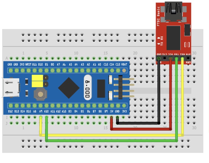
Here is a pin to pin map of the connection
FTDI STM32
With this done, we then change the position of the board’s state jumper to position one (as shown in the gif below), so as to put the board in programming mode. Press the reset button on the board once after this and we are ready to upload the code.
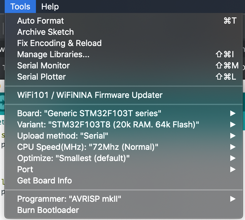
On the computer, ensure you select “Generic STM32F103C board” and select serial for the upload method after which you can hit the upload button.
Once the Upload is complete, change the state jumper to position “0” this will put the board in “run” mode and it should now start running based on the code uploaded. At this point, you can disconnect the FTDI and power the board over its USB. In case the code does not run after powering, ensure you have restored the jumper properly and recycle power to the board.
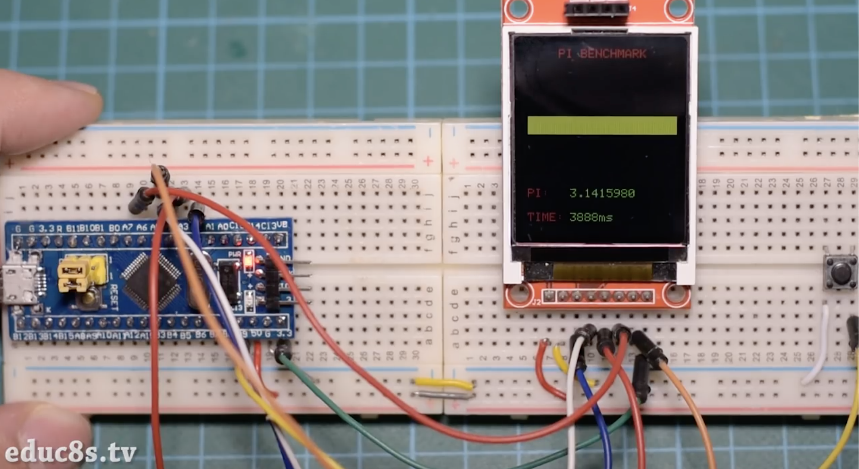
With the code complete, follow the upload process described above to upload the code to your setup. You should see the display come up as shown in the Image below.
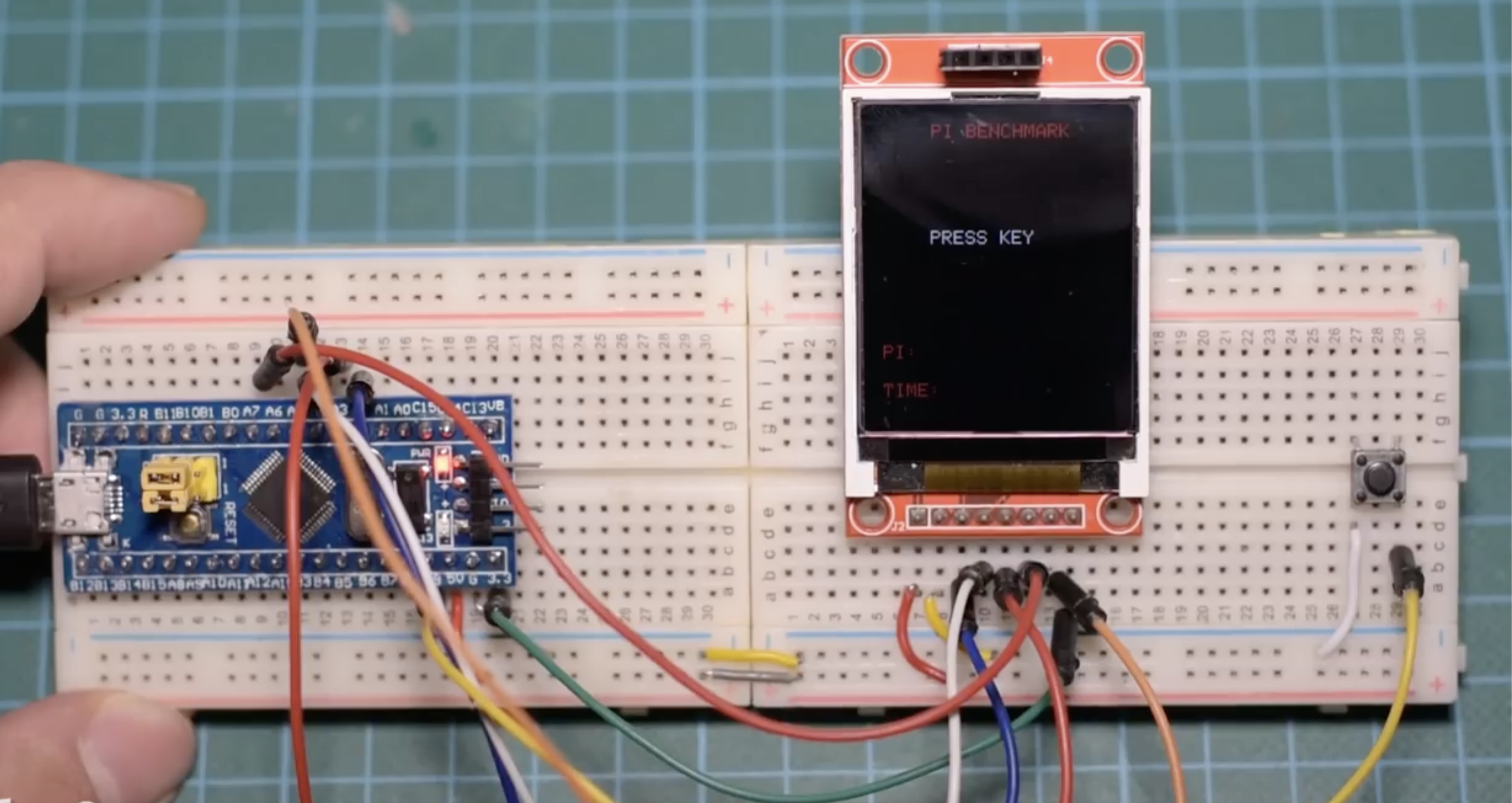
Press the pushbutton to start the calculation. You should see the progress bar slide gradually until the end. At the end of the process, the value of Pi is displayed along with the time which the calculation took.
The same code is implemented on an Arduino Uno. The result is shown in the image below.
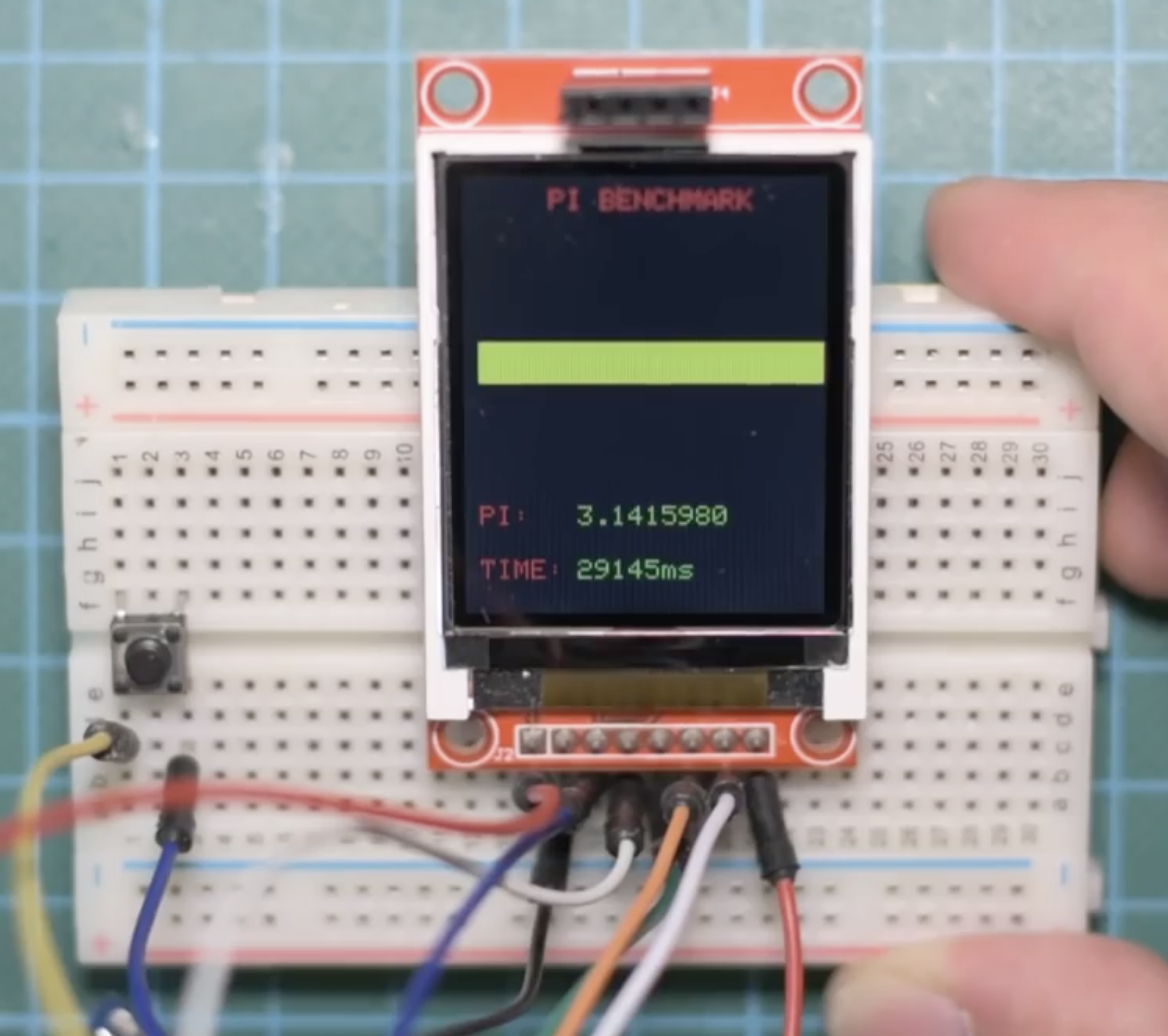
Comparing these two values, we see that “Blue Pill” is over 7 times faster than the Arduino Uno. This makes it ideal for projects which involves heavy processing and time constraints. The small size of the Blue pill also serves as an advantage here as it is only a bit bigger than the Arduino nano and it can be used in place where the Nano won’t be fast enough.
That’s it for today’s tutorial guys. What will you be building with the Blue Pill? feel free to share along with any questions you might have, under the comment section.
Источник: