


Let’s code with STM32 NUCLEO
Содержание
Today we present the first steps with the NUCLEO development boards, produced by STMicroelectronics, that can help us to move towards the ARM 32-bit world with simplicity and great performances , keeping a compatibility with Arduino expansion connectors so that we can use its commonly available shields.
The success of Arduino and its countless shields, kicked off in recent years the birth of several compatible development boards designed to help us creating in a short time, at low cost and easily, great and even complex electronic applications. Some of these boards are simple clones, other are at much higher level having better performances and memory storage.
Among those, a really interesting solution is represented by the development boards family called NUCLEO made by STMicroelectronics, a semiconductors leader company.
In this post we will examine the NUCLEO F401RE board that is among the best performing in the series, not only because it is based on an ARM processor with a 84 MHz clock, a 512 Kb flash memory and an integrated floating-point unit, but also for a number of interesting features that we will see together.
We will also see how to program it and test it by using some development environments available and a first sample program.
The board name comes from the microcontroller mounted on the board (STM32F401) which is its heart. The whole series of NUCLEO development boards is equipped with a STM32 microcontroller based on ARM Cortex-M family, adopting a 32-bit RISC architecture. Each NUCLEO board differs for performances, power consumption, clock frequency and flash memory capacity of the STM32 microcontroller in figure.

The family of the NUCLEO board.
All the boards, however, have the same layout and the same form, which is shown in next figure.
From here on, we will analyze the NUCLEO model F401 and we will move our first programming steps, but many of the aspects and features that we will see later will be valid for any other NUCLEO board.
One of the first aspects that we can note is the presence of many contacts on card’s border, including the now famous female contacts connector compatible with the Arduino shield. Externally, however, two double strips of male contacts (one per side) are what STM calls “Morpho” pinout, used on other STM development boards.
In figure Arduino pinout is shown in purple, while the Morpho pinout is in blue: notice how all Arduino pins are remapped exactly on Morpho inner pin strip (connectors CN7 and CN10): this allows us to always have access to Arduino pinout also once a shield is plugged on the board. This helps us to debug software easily and to use those outputs when some shields don’t pass-through.

NUCLEO board connectors’ pinout
CN7 and CN10 connectors pins are not connected to Arduino compatible connector and they provide other proprietary I/O or power connector typical of STM32 microcontrollers. This allows the card to be used in other projects which require greater connectivity.
There is more; CN7 and CN10 Morpho connectors are replicated also on the board backside (always with male contacts strips), allowing you to mount the NUCLEO board on another board that could be seen as a new shield and that can access (also and not only) to Arduino pinout.
Another interesting feature is the presence on the NUCLEO board of a PCB area that is always part of the board, but serves exclusively to its programming and debugging. It is the PCB part, looking in figure, that is close to the two small buttons and that can easily be physically split; this helps reducing the NUCLEO board size that actually runs the applications.

Layout of the NUCLEO board.
This portion of the circuit is independent from the rest and is always equipped with a STM32 microcontroller suitably programmed during manufacture to manage the functions of a real programmer and debugger for the STM8 and STM32 family of microcontrollers.
Specifically, it is the ST-LINK/V2 debugger (further details in the box on these pages) manufactured by STMicroelectronics that is in our case integrated on the same board, without needing additional hardware (and costs). In fact, the same USB cable, which is used to power up will also serve to program and debug our NUCLEO board, as we shall see later.
Once you’ve programmed your board you can tear-off the debugger board and have in this way a very compact microcontroller board. It will always be possible to program and debug the NUCLEO board again, by connecting with external cables, the SWD connector (CN4) on the debug board to Morpho connector (CN7) pins 15 and 17 on the NUCLEO board. The SWD (Serial Wire Debug) protocol recently introduced by ARM and implemented in all Cortex-M microcontroller family is transported, in fact, over only two wires instead of the five-wire JTAG that we are usually accustomed to.
So, unless special needs and at least in these early stages of development, we do not recommend to separate the two boards, because having all integrated is much more comfortable for our purpose (taking first steps with our STM32 system) and also we will have a unique power that is supplied from the USB cable through CN1.
Since we’re talking about power supply, let’s discuss further on the subject: the NUCLEO board (debugger ST-LINK / V2 and board with STM32 micro) is powered by the MINI-USB connector that provides 5 V.
We can use also an external power supply, because, when we will use it in our final application probably we won’t have a PC but rather a battery or an external power supply.
So we can power the VIN pin connector CN6 (Arduino compatible) if we have a power source between 7 V and 12 V, or E5V pin on connector CN7, if we have a stable 5V. In both cases, however, we should remember to move the triple jumper JP5 (connected, by default, to U5V) to position E5V. It is also important to note that if you are using an external power supply, it will always be possible to program and debug the device taking care to insert the USB cable only after powering the board, otherwise there will be a conflict and the programming will fail.
To complete the first description of this board, a note on the two buttons and two LEDs on the NUCLEO board; B1 is a button used by the programmer and connected to Morpho connector (CN7) pin 23, while B2 is the reset button. When plugging a shield on top of the NUCLEO is good to remove covers from the colored buttons, otherwise the buttons B1 and B2 could be pressed accidentally, with annoying consequences. The LED LD2 is usable by the programmer and is connected to pin 6 of CN5 connector (also in this case the compatibility with Arduino Uno is kept, since its D13 is connected on a “user LED”) while the LED LD3 is red and lights when the board is regularly powered.
Finally, on the ST-LINK/V2 board section there is a multi-color LED LD1 that identifies the different steps of communication between the debugger and the STM32 micro; every color and flashing pattern indicates a programming phase. Without going into too much detail, let’s say that this LED will flash quickly during the programming phase, to remain solid green when it is successful.
Finally, the jumper JP6 (called IDD) located in the NUCLEO, can be disconnected if we want to control the power consumption of the microcontroller during operations; to do that, connect to JP6 jumper pins a current meter to measure DC current (JP6 is in series with 3.3 V voltage that powers the microcontroller). Knowing the real time consumption of an operating NUCLEO lets you know the available battery capacity (if the application is designed to run on batteries).
The jumper JP1, in the ST-LINK/V2, is normally left unconnected, but should be short-circuited in case the board is powered by the USB connector connected to a charger and not to a PC (otherwise the led LD3 will not switch on).
Technical features
After an initial presentation, we can analyze which are the features we like more in the F401RE STM32 microcontroller.
It is an ARM Cortex-M4 with a 32-bit floating-point unit and with a clock frequency that, by properly configuring the internal registers, can scale up to 84 MHz, the whole with a really low current consumption (even around 9 uA). The fact of being 32-bit and having a ‘floating-point unit” greatly increases the system performance especially in case of complex algorithms.
On memory side, it has 512 Kb Flash memory where our code resides and 96 KB of SRAM used for program execution. Talking about peripherals it is present a 12-bit analog to digital converter (ADC) that can be shared over sixteen channels; six 16-bit timers and two 32-bit timers that can be configured in various ways including the classic IC (input capture), OC (output compare) and PWM (pulse wide modulation), and other two timers used in watchdog mode.
There are, of course, numerous communication interfaces: three I2C interfaces, three USART interfaces (two of which may even reach a speed of 10 Mbit / s), four SPI interfaces at 42 Mbit / s: all available on I/O pins that are also remapped on Morpho connectors (CN7 and CN10). The I/O pins are also tolerant to 5 V and then, if configured as an input, will be able to accept a 5V TTL signals without damaging the internal drivers.
Among the interfaces we count the debugging ones too, the classic JTAG and the SWD introduced by the most recent ARM Cortex family and also used in the NUCLEO board (see dedicated box, in these pages).
Finally we have an RTC with integrated calendar and full-speed USB 2.0 port that can operate not only in the traditional device mode, but also in host mode (OTG), or allowing the micro to communicate with USB devices such as mice, keyboards, storage devices and other.

Comparison of NUCLEO board with Arduino UNO and Arduino TWO.

Compared to Arduino
With all of these important features, a comparison with the Arduino platform is definitely due!
Surely, we are facing a very powerful board and at the same time, it is so well “boxed” to be used by the many newcomers who day after day are entering the world of embedded programming. It is true that Arduino now has a wider spread and a very active community, but also the NUCLEO series looks so promising.
In Table we compared NUCLEO to the most common Arduino board (Arduino UNO) and to one of the best performing (Arduino DUE) that is closest to the technology exploited by the ARM NUCLEO because it has a ARM Cortex-M3.
Please note that we do not want to find a winner, since each of the three boards has special characteristics that make them preferable depending on the real use cases, but surely in this comparison the NUCLEO board can certainly be a protagonist.
Let us first examine the comparison between NUCLEO and Arduino UNO board; if from a technical point of view the first has the best in terms of performances and quality, there are other factors to consider. NUCLEO board hasn’t an external EEPROM memory and even the micro STM32 hasn’t an internal EEPROM memory to store permanent variables in case of board reboot, while Arduino can count on Atmel microcontroller EEPROM. In addition, NUCLEO lacks of an external power connector in case we want to use shields requesting a power voltage above 5V or an external power supply.
Nothing, however, to worry about because this can become a stimulus to create our dedicated shield, as we shall see in future post.
The comparison between NUCLEO board and Arduino DUE is harsher because they mount the same family of microcontrollers (ARM Cortex-M), but the NUCLEO has a Cortex-M4 despite of the Cortex-M3 on Arduino DUE and has the floating-point unit too.
So in case you wish to use algorithms that use floating-point heavily, the C code will be written in the same way on both boards but the compiler for Cortex-M4 will generate far fewer instructions which will be executed quicker and also with significant performance increase in term of low memory footprint.
The clock frequency and flash memory are comparable, Arduino DUE has a larger number of I/O modules, but those pins can’t bear (if configured as input) voltages above 3.3 V, limiting the use of Arduino shields that request 5 V.
Mbed Programming
Now we come to the interesting part, which is how to program the NUCLEO board. Even if the board is compatible with the Arduino shield, it is not with its programming environment; then a program written for Arduino cannot be compiled “as-is” for NUCLEO. This problem is not as great as it might seem, because as we do with Arduino, the NUCLEO programming is in C (then the code done for a board is easily portable without too many changes to the other) and also because we have lots of good IDE to move our first steps.
Let’s see how you program the NUCLEO: first connect the board to the PC via a MINI-USB cable; LEDs LD1 and LD3 will light up and start a small sample firmware preloaded in Flash memory that will flash the LED LD2 in different patterns that we can change by pressing B2 button.
We need anyway to load our code, so we will have first to download the driver to manage the ST-LINK/V2 embedded debugger; This is a zip file available on www.st.com/stm32nucleo after selecting the corresponding NUCLEO board (in our case the F401RE). Proceed to install it by executing the batch file inside the zip or manually from the device list. It is not necessary, but together with the driver you can also download an executable (ST-LinkUpgrade.exe) to update the ST-LINK/V2 debugger firmware; just press the button “Device Connect” to check the version and then “Yes” to perform the operation.
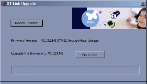
ST-LinkUpgrade.exe updates the firmware of the integrated debugger of NUCLEO.
At this point we have everything ready and we could even avoid installing a development environment, because the programming can be done directly online. This is possible thanks to ARM mbed, an online platform designed and developed by ARM to enable the development and deployment of devices based on 32-bit ARM Cortex-M family (we’ve already talked about in previous issues of the magazine). It is, in short, an on-line IDE, free, simple and fast that enables you to edit the code and compile it directly on your browser. The cloud compiler is a C / C ++ (ARMCC); the development toolchain is continuously reviewed and kept up to date and our code will be saved in a private cloud we can access whenever we connect with our account. You will obviously be required to sign up here: http://mbed.org/ to be redirected, the next time, directly to the IDE itself, which will appear as in figure.

mbed online IDE.
Although everything is online, the editor is really friendly, it has syntax coloring, online help, references to functions of the various classes and is very fast. Another thing that makes it interesting is the ability to access a vast database of projects written by other ARM programmers and import them directly into your workspace. Also we can make our code public and accessible to the ARM mbed community, keeping it updated with an integrated version-control tool and being able to upload further versions.
After selecting our board by pressing the top right button we can decide whether to load in our working environment one of the many projects that have already been written for the selected board (and edit them according to our needs via “New” and then “New Program” buttons), or you can import a project written by other programmers by choosing its tagged keywords (“Import” button). In the first figure you can see the wizard to create a sample project that uses the NUCLEO board PWM, while in the second is represented a simple code that manages LED LD2.
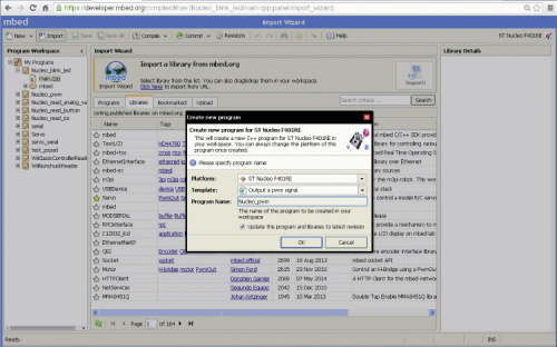
mbed Wizard to generate our first project

Use of mbed to have a LED flashing
The code, also reported in Listing1, is very simple and speaks for itself; in short we can see that it is enough to include mbed.h and then we can choose which led to be managed (LED1 is a #define that matches a LED port in our board) making it flash with a variable by delay using the wait () method (it takes as a parameter a float value in seconds).
Listing 1
Similarly the “serial” object allows us to use a serial port (USBTX and USBRX #defines are remapped on pins D0 and D1 on Arduino connector) that with the method printf () will print a debug string on the virtual COM port of the PC (generated by the ST-LINK/V2 embedded module on the board) through the same USB cable.
Once our project is done, it will be even easier to load it to the board without the need for third-party software programs. You have noted that when plugging in the board through an usb cable to the PC, the NUCLEO is seen as a mass memory by the operating system, because the ST-LINK/V2 programmer also acts as a “virtual mass storage device”. It is obviously not a pendrive where you can store your data, but it is an original solution to transfer our code on the STM32 flash memory.
When you press “Compile” on the IDE (top up in the command bar) the project will be compiled in the cloud and if there are no errors, the generated binary file will be downloaded by your browser on your local PC; at this point just drag it to the NUCLEO “mass storage”, wait a few seconds and when the LED LD1 has finished flashing the code will run from Flash.
If we wanted to speed things up we might also configure your browser in order to use the new drive as the destination for our downloads, so just press the compile button and wait for the NUCLEO board to run our code.
Onboard Debug Unit
This we have just seen is the easiest way to program our NUCLEO board. Quick and easy, but it certainly has the disadvantage of needing to be connected to internet because the compiling is done on the cloud, and in any case Mbed can’t debug our code step by step. STMicroelectronics indicates a series of compilers and development environments (EWARM, MDK-ARM and TrueSTUDIO) that allow us to work off-line and being able to follow the code flow by inspecting memory and registers values for each instruction coded.
They are not free, but you can download a free trial version for a limited time or limiting the code size to a max of 32 kB, good enough to do some test project.
There are also free alternatives without limits, such as “Em :: Blocks”, also thought for many other embedded devices and whose appearance is shown in figure. In this way we can use our ST-LINK/V2 like a real debugger, useful in cases where we want to investigate the behavior of some bug or to better analyze the state of our variables, by inserting breakpoints on code lines.

Step by step debugging using the Em :: Blocks IDE.
It is important to know that we should not necessarily rewrite our Em :: Blocks project from scratch, but we can also import a project created with Mbed since Em :: Blocks IDE will take care to convert it to a compatible project. Obviously this is possible due to the fact that Mbed, in addition to saving our projects in a private cloud, let us export our software as a zip file or in many other projects’ formats compatible with some of the development environments used, including precisely Em :: blocks.
There are still many interesting aspects to be illustrated about this board, but for now we stop here, hoping to have laid a secure foundation for your next project with this new STM32 board that will allow you to enter the ARM mbed world and beyond.
Источник: