


Lab: Controlling a Stepper Motor With an H-Bridge
Содержание
- What You’ll Need to Know
- Things You’ll Need
- Prepare the breadboard
- Set up the H-bridge
- Connect the H-bridge
- Connect the motor to the H-bridge
- Connect the H-Bridge to the microcontroller
- Program the microcontroller
- Attach something to the stepper
- Unipolar Stepper Control
- Note for 3.3V Microcontrollers
Stepper motors are motors that have multiple coils in them, so that they can be moved in small increments or steps. Stepper motors are typically either unipolar or bipolar, meaning that they have either one main power connection or two. Whether a stepper is unipolar or bipolar, however, you can control it with an H-bridge. This lab shows you how to set up a unipolar stepper motor using an H-Bridge. You can use the same control circuit with a bipolar motor too, however.
What You’ll Need to Know
To get the most out of this lab, you should be familiar with the following concepts. You can check how to do so in the links below:
Things You’ll Need
Figures 1-7 are the parts you’ll need for this exercise.
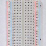 Figure 1. A short solderless breadboard.
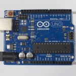 Figure 2. An Arduino Uno.
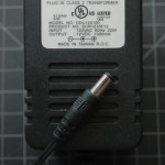 Figure 5. DC Power Supply
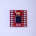 Figure 8. Motor Driver (H-bridge), model TB6612FNG
Prepare the breadboard
Connect power and ground on the breadboard to power and ground from the microcontroller. On the Arduino module, use the 5V and any of the ground connections. Figure 9 shows how this can be done on an Arduino Uno.
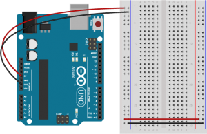
Figure 9. An Arduino Uno on the left connected to a solderless breadboard, right.
Set up the H-bridge
Figure 10 is the top view of a H-bridge IC.
This example uses an H-bridge integrated circuit, the Texas Instruments L293NE or Texas Instruments SN754410. Many distributors such as Digikey, SparkFun, Mouser and Jameco sell them.
For 3.3V microcontrollers like the Nano 33 IoT, check out the notes on the Toshiba TB6612FNG H-bridge below.
The H-bridge will be used in a manner very similar to the DC Motor Control lab. But because the stepper has two coils instead of one, it’ll be as if you were driving two motors with the H-bridge.
How your H-bridge works
The L293NE/SN754410 is a very basic H-bridge. It has two bridges, one on the left side of the chip and one on the right, and can control 2 motors. It can drive up to 1 amp of current, and operate between 4.5V and 36V. The small DC motor you are using in this lab can run safely off a low voltage so this H-bridge will work just fine.
The H-bridge has the following pins and features:
- Pin 1 (1,2EN) enables and disables our motor whether it is give HIGH or LOW
- Pin 2 (1A) is a logic pin for our motor (input is either HIGH or LOW)
- Pin 3 (1Y) is for one of the motor terminals
- Pin 4-5 are for ground
- Pin 6 (2Y) is for the other motor terminal
- Pin 7 (2A) is a logic pin for our motor (input is either HIGH or LOW)
- Pin 8 (VCC2) is the power supply for our motor, this should be given the rated voltage of your motor
- Pin 9-11 are unconnected as you are only using one motor in this lab
- Pin 12-13 are for ground
- Pin 14-15 are unconnected
- Pin 16 (VCC1) is connected to 5V
Figure 11 below shows a diagram of the H-bridge and which pins do what in our example. Included with the diagram is a truth table indicating how the motor will function according to the state of the logic pins (which are set by our Arduino).
For this lab, both enable pins are connected to 5V to keep them HIGH all the time so the bridge is constantly enabled. The motor logic pins also connected to designated digital pins on your Arduino so you can set them HIGH and LOW to control the stepper. The motor supply voltage connects to the voltage source for the motor, an external 12V DC power supply. Not all steppers run on 12V, but the one used for this example does. Check your stepper’s datasheet before you power the H-bridge.
Connect the H-bridge
Connect the H-bridge as shown in Figure 12 and Figure 13:
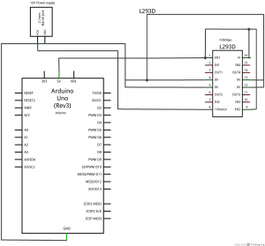
Figure 12. Schematic view of an h-bridge connected to an Arduino for driving a stepper motor.
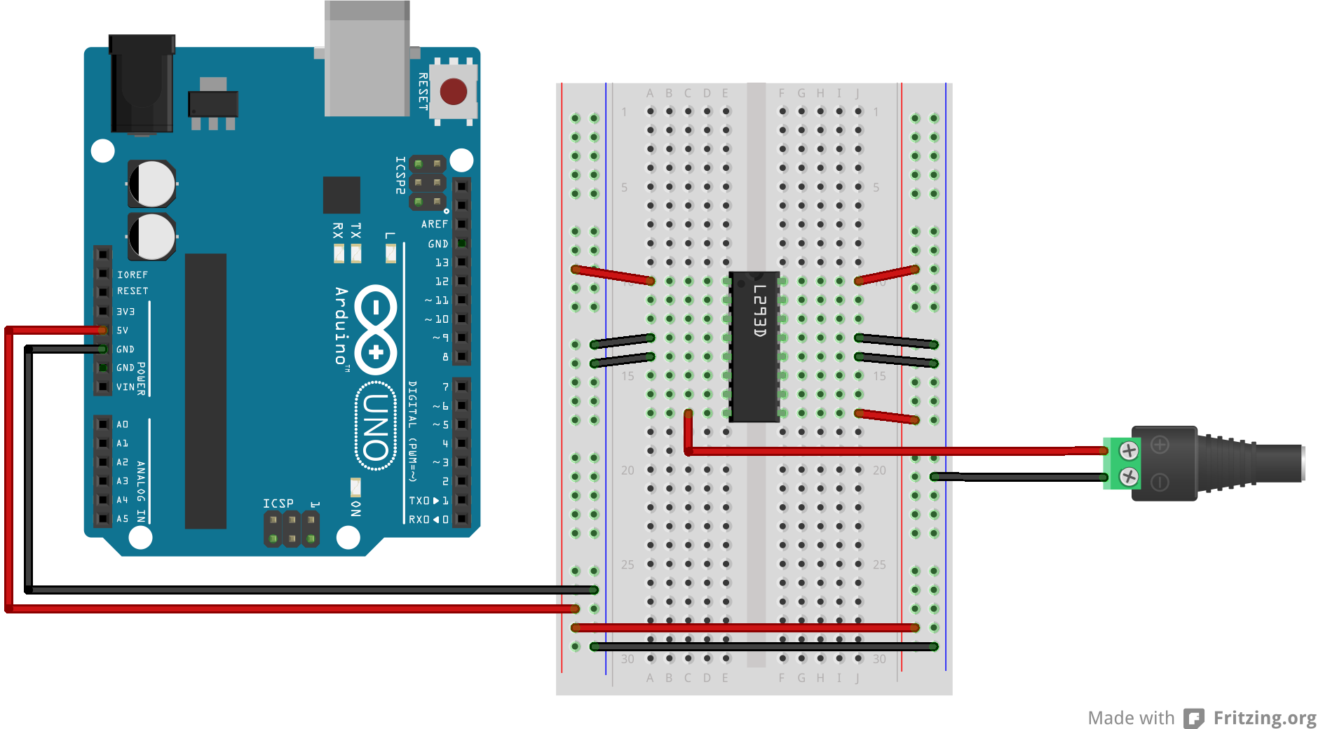
Figure 13. Breadboard diagram of an H-bridge and an Arduino wired for control of a stepper.

How the stepper motor works
The stepper motor has two coils to control it as shown in Figure 14. Each coil has a center connection as well, and the center connections are joined together, which is what makes this a unipolar stepper. If you don’t connect the center connection, then the motor will work very much like a bipolar stepper, each coil operating independently. This is how you’ll use it for this exercise. Each coil will connect to one side of the H-bridge. The pink and orange wires (wires number 2 and 4) are connected tothe first coil. They will connect to one side of the bridge, while the yellow and blue wires (wires number 3 and 5) are the other coil, and will connect to the other side of the bridge. In this case, the red wire, pin 1, will not be used.
Connect the motor to the H-bridge
Connect the motor to the H-bridge as shown in Figure 15 and Figure 16:
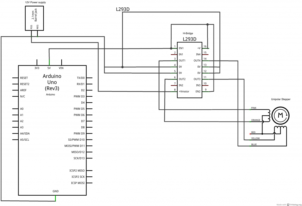
Figure 15. Schematic of an Ardiuino and an H-bridge, with the stepper motor added.
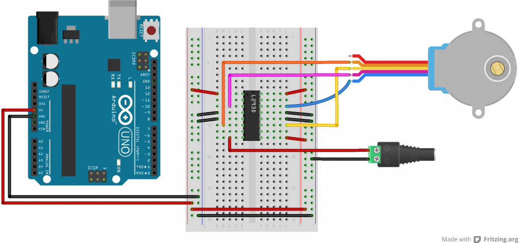
Figure 16. Breadboard view of an h-bridge connected to an Arduino, with the stepper motor added.
Note that the H-bridge’s DC power is coming from the 12V DC connector. It shares a common ground with the Arduino, though. You could also use the Arduino’s DC power jack and power the motor from the Vin pin.
Connect the H-Bridge to the microcontroller
The H bridge’s control inputs are connected to the microcontroller’s input pins digital 8 through 11 as shown in Figure 17 and Figure 18:
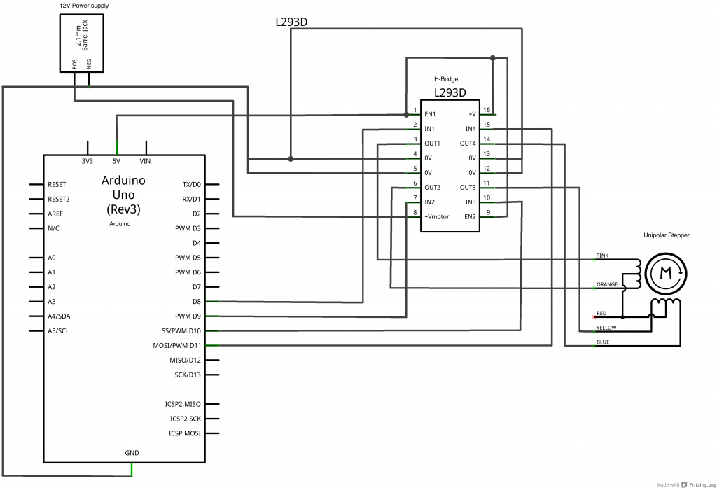
Figure 17. Schematic drawing of an h-bridge and stepper motor connected to an Arduino., with the control wires added.

Figure 18. Breadboard drawing of an h-bridge and stepper motor connected to an Arduino, with the control wires added.
Once you have those connected, you’re ready to program the microcontroller.
Program the microcontroller
Program the microcontroller to run the stepper motor through the H-bridge using the stepper library. For your first program, it’s a good idea to run the stepper one step at a time, to see that all the wires are connected correctly. If they are, the stepper will step one step forward at a time, every half second, using the code below:
Once you’ve got that working, try making the stepper move one whole revolution at a time. The number of steps per revolution will depend on your individual stepper, so check the data sheet for the number of steps per revolution:
With a high-step-count stepper, you may need to change the speed. If the motor steps are run too fast, the motor coils don’t have a chance to energize and de-energize in order to step the motor.
Attach something to the stepper
If you want to mount an arm or pointer to the stepper motor, you need to make a hole for the pointer that fits the shaft perfectly. You could measure this with a caliper.
Unipolar Stepper Control
The steps above showed you how to control a bipolar stepper, but the motor shown was actually a unipolar motor. Remember the red wire you didn’t connect? That wire connects the two coils and can act as a common power source or ground wire. To use the motor as a unipolar motor, try connecting that wire (wire 1) of the motor to the +12V power supply from the DC power jack.
Note for 3.3V Microcontrollers
The H-bridge used in this lab are great if you’re using an Uno or other microcontroller that operates at 5 volts, but if you’re using one of the more modern Arduino or Arduino-compatible boards, it probably operates at 3.3 volts. For example, all of the M0-based controllers, like the MKR series or the Adafruit Feather M0 series, and the ESP8266 all operate at 3.3 volts. They do not supply a high enough logic voltage for the L293 H-bridge. For these boards, you might want to use a 3.3-volt compatible board, like the Toshiba TB6612FNG H-bridge. There’s both a Sparkfun breakout board and an Adafruit breakout board for this part, and A Pololu breakout board as well. It can handle a motor supply voltage up to 15V, and it operates on a logic voltage of 2.7–5.5V. It can control an output current of 1.2A. It’s similar to the L393, in that it has two H-bridges, each with two logic inputs and two motor outputs. The enable inputs on the Toshiba part are called PWM inputs, because they are expected to be used for speed control like you saw with the L293 above. There’s also a Standby pin that you have to connect to voltage through a 10-kilohm pullup resistor to activate the h-bridges. Figure 19 shows the schematic diagram and Figure 20 shows the breadboard view of this circuit explained above.
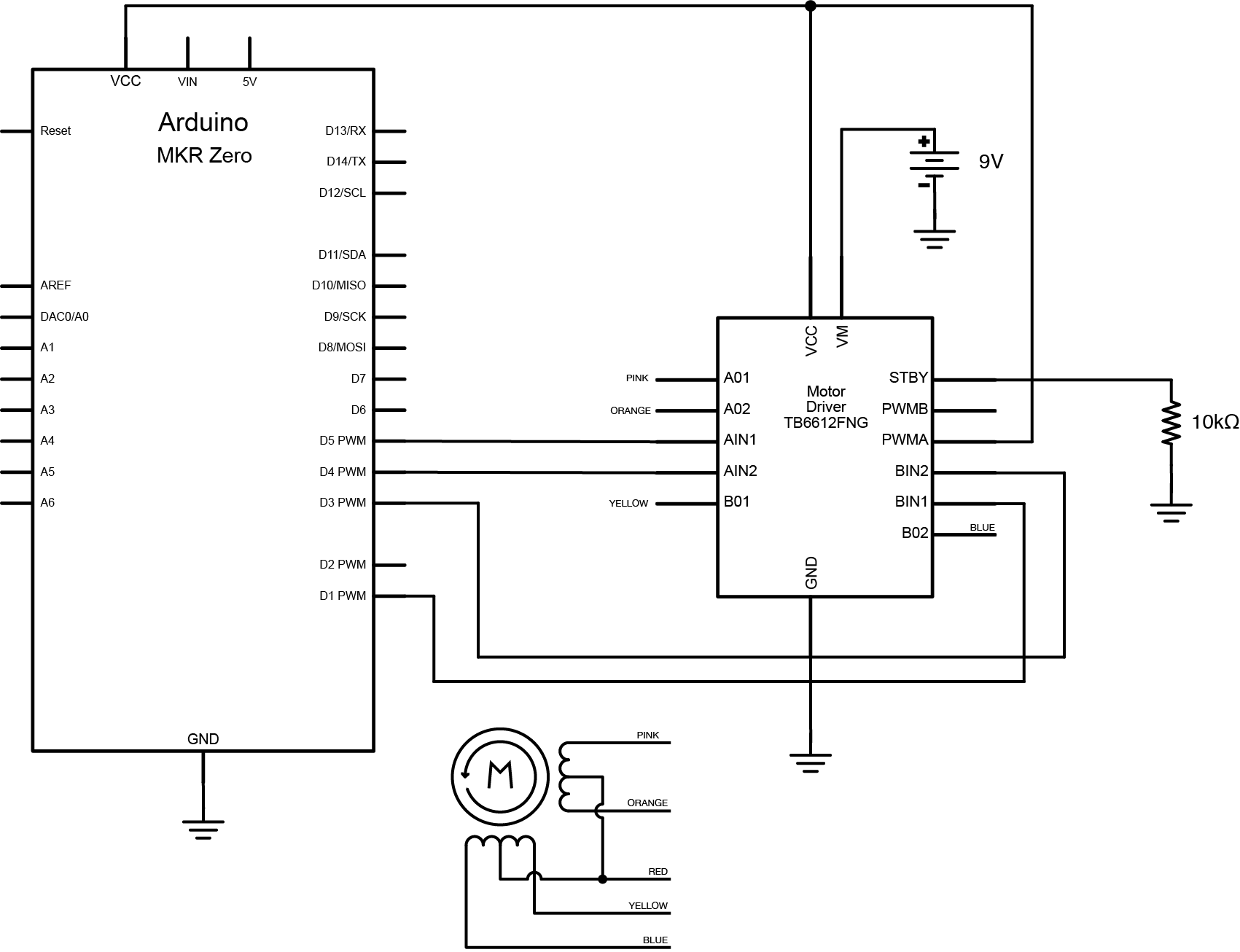
Figure 19. Schematic of TB6612 H-bridge controlling a stepper
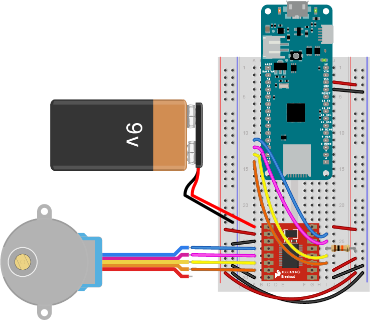
Figure 20. Breadboard view of TB6612 H-bridge controlling a stepper
Источник: