


Spi h скачать библиотеку
This library allows you to communicate with SPI devices, with the Arduino as the master device.
To use this library
#include SPI.h
A Brief Introduction to the Serial Peripheral Interface (SPI)
Serial Peripheral Interface (SPI) is a synchronous serial data protocol used by microcontrollers for communicating with one or more peripheral devices quickly over short distances. It can also be used for communication between two microcontrollers.
With an SPI connection there is always one master device (usually a microcontroller) which controls the peripheral devices. Typically there are three lines common to all the devices:
- MISO (Master In Slave Out) — The Slave line for sending data to the master,
- MOSI (Master Out Slave In) — The Master line for sending data to the peripherals,
- SCK (Serial Clock) — The clock pulses which synchronize data transmission generated by the master
and one line specific for every device:
- SS (Slave Select) — the pin on each device that the master can use to enable and disable specific devices.
When a device’s Slave Select pin is low, it communicates with the master. When it’s high, it ignores the master. This allows you to have multiple SPI devices sharing the same MISO, MOSI, and CLK lines.
To write code for a new SPI device you need to note a few things:
- What is the maximum SPI speed your device can use? This is controlled by the first parameter in SPISettings . If you are using a chip rated at 15 MHz , use 15000000. Arduino will automatically use the best speed that is equal to or less than the number you use with SPISettings .
- Is data shifted in Most Significant Bit (MSB) or Least Significant Bit (LSB) first? This is controlled by second SPISettings parameter, either MSBFIRST or LSBFIRST. Most SPI chips use MSB first data order.
- Is the data clock idle when high or low? Are samples on the rising or falling edge of clock pulses? These modes are controlled by the third parameter in SPISettings .
The SPI standard is loose and each device implements it a little differently. This means you have to pay special attention to the device’s datasheet when writing your code.
Generally speaking, there are four modes of transmission. These modes control whether data is shifted in and out on the rising or falling edge of the data clock signal (called the clock phase), and whether the clock is idle when high or low (called the clock polarity). The four modes combine polarity and phase according to this table:
| Mode | Clock Polarity (CPOL) | Clock Phase (CPHA) | Output Edge | Data Capture |
| SPI_MODE0 | 0 | 0 | Falling | Rising |
| SPI_MODE1 | 0 | 1 | Rising | Falling |
| SPI_MODE2 | 1 | 0 | Rising | Falling |
| SPI_MODE3 | 1 | 1 | Falling | Rising |
Once you have your SPI parameters, use SPI.beginTransaction() to begin using the SPI port. The SPI port will be configured with your all of your settings. The simplest and most efficient way to use SPISettings is directly inside SPI.beginTransaction(). For example:
SPI.beginTransaction( SPISettings (14000000, MSBFIRST, SPI_MODE0));

If other libraries use SPI from interrupts, they will be prevented from accessing SPI until you call SPI.endTransaction() . The SPI settings are applied at the begin of the transaction and SPI.endTransaction() doesn’t change SPI settings. Unless you, or some library, calls beginTransaction a second time, the setting are maintained. You should attempt to minimize the time between before you call SPI.endTransaction() , for best compatibility if your program is used together with other libraries which use SPI.
With most SPI devices, after SPI.beginTransaction() , you will write the slave select pin LOW, call SPI.transfer() any number of times to transfer data, then write the SS pin HIGH, and finally call SPI.endTransaction() .
Connections
The following table display on which pins the SPI lines are broken out on the different Arduino boards:
| Arduino / Genuino Board | MOSI | MISO | SCK | SS (slave) | SS (master) | Level |
| Uno or Duemilanove | 11 or ICSP-4 | 12 or ICSP-1 | 13 or ICSP-3 | 10 | — | 5V |
| Mega1280 or Mega2560 | 51 or ICSP-4 | 50 or ICSP-1 | 52 or ICSP-3 | 53 | — | 5V |
| Leonardo | ICSP-4 | ICSP-1 | ICSP-3 | — | — | 5V |
| Due | SPI-4 | SPI-1 | SPI-3 | — | 4, 10, 52 | 3,3V |
| Zero | ICSP-4 | ICSP-1 | ICSP-3 | — | — | 3,3V |
| 101 | 11 or ICSP-4 | 12 or ICSP-1 | 13 or ICSP-3 | 10 | 10 | 3,3V |
| MKR1000 | 8 | 10 | 9 | — | — | 3,3V |
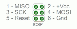
Note that MISO, MOSI, and SCK are available in a consistent physical location on the ICSP header; this is useful, for example, in designing a shield that works on every board.
Note about Slave Select (SS) pin on AVR based boards
All AVR based boards have an SS pin that is useful when they act as a slave controlled by an external master. Since this library supports only master mode, this pin should be set always as OUTPUT otherwise the SPI interface could be put automatically into slave mode by hardware, rendering the library inoperative.
It is, however, possible to use any pin as the Slave Select (SS) for the devices. For example, the Arduino Ethernet shield uses pin 4 to control the SPI connection to the on-board SD card, and pin 10 to control the connection to the Ethernet controller.
Examples
-
: Read air pressure and temperature from a sensor using the SPI protocol. : Control a AD5206 digital potentiometer using the SPI protocol.
Last revision 2019/12/24 by SM
Functions
See also
Corrections, suggestions, and new documentation should be posted to the Forum.
The text of the Arduino reference is licensed under a Creative Commons Attribution-ShareAlike 3.0 License. Code samples in the reference are released into the public domain.
Источник: