


Program RGB LEDs with Arduino
Содержание
- Materials List
- RGB LED Wiring Diagram for Arduino
- How to use RGB LEDs
- A Brief Overview of Coding Arduino
- Program an RGB LED with Arduino
- Control Color Patterns with an RGB LED
- Program RGB LEDs with Arduino
- Give me One Week in your Inbox.
RGB LEDs can be used to display a variety of colors without the need to wire multiple different colored LEDs at once. In this article, I’ll show you how to wire and program an RGB LED using Arduino for your next technicolor project.
Table of Contents
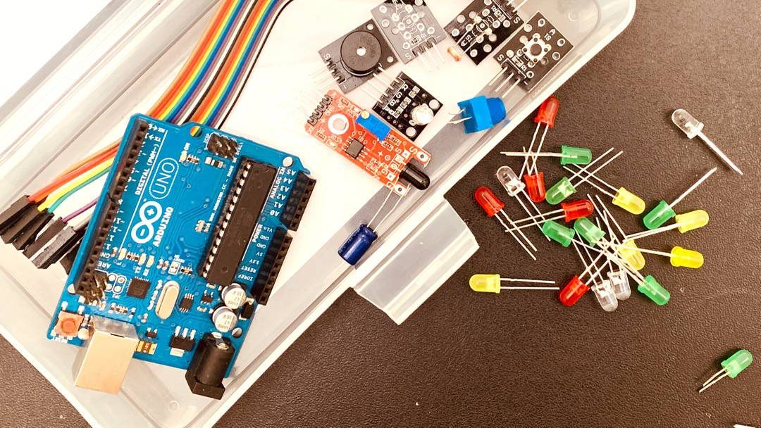
Materials List
Here’s a list of what you’ll need for this project:
RGB LED Wiring Diagram for Arduino
We can use the wiring diagram to connect the RGB LED to our breadboard. First, place the LED on the breadboard so that all four pins are in different numbered columns.
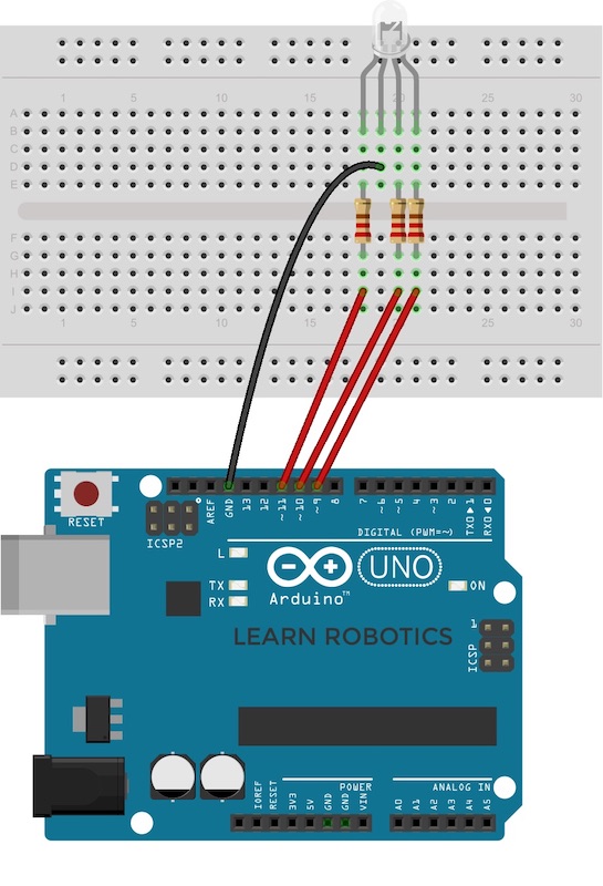
Most LEDs have a polarity. This one has a common cathode configuration, which means we’re going to be plugging the longer leg into the ground.
Then we’ll connect the remaining legs from left to right (red, ground, blue, green). Double-check your LEDs datasheet to ensure you have the proper configuration.
Next, add the resistors to the breadboard. Each color pin needs its resistor. This is to limit the amount of current that the LED is getting so that we don’t burn it out.
Then, take the jumper wires and connect the red pin’s resistor side to the Arduino digital signal pin. Start with the red jumper wire and plug it into pin 11. Connect the Cathode pin to Ground on the Arduino. Then attach the blue pin’s resistor side to pin 10. Finally, run a jumper wire from the green pin’s resistor side to pin 9.
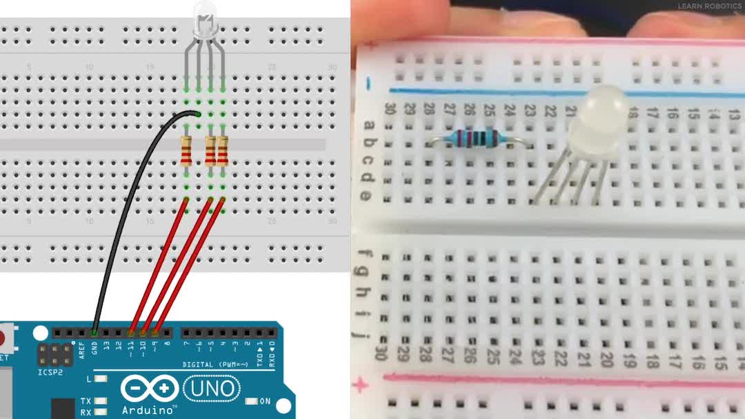
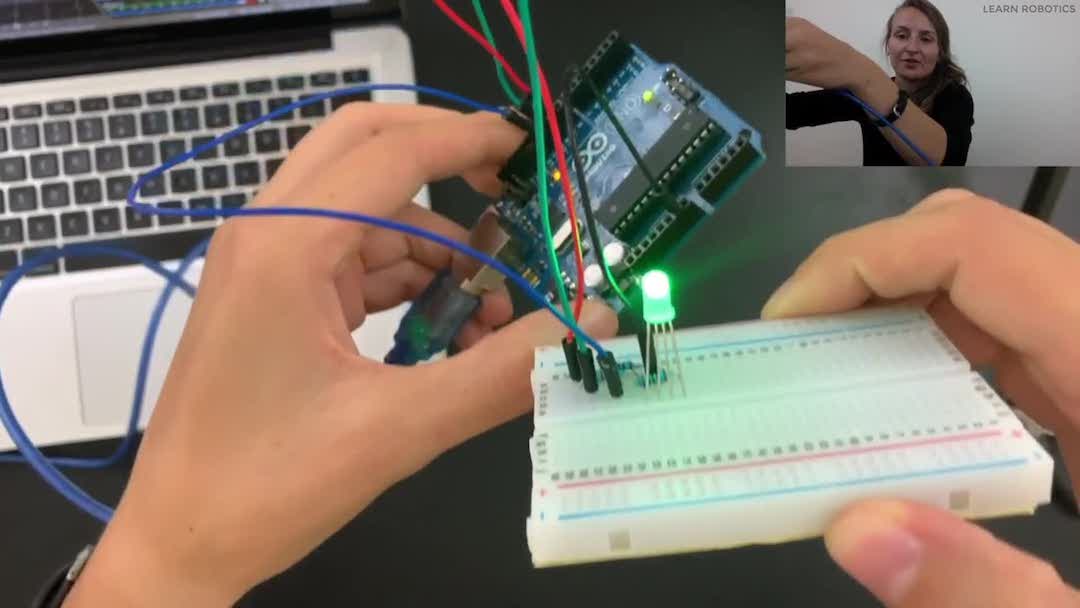
Here’s what it should look like when you’re finished:
If you want, you can also snip the pins on the LED so that they sit closer to the board.
For more permanent projects, I highly recommend trimming the legs to keep them closer to the board. (Keep the ground pin a little longer so that you can keep track of the orientation.)
How to use RGB LEDs
There are many projects you can do with RGB LEDs; however, the most popular is creating light shows. Let’s explore RGB color patterns by using an RGB color picker.
We can create a map between the red, green, and blue values to create custom colors. Then, we can use delays to develop transitions and patterns.
Now that we have everything wired up, it’s time to head on over to the software. If you’ve never used Arduino before this is a good time for you to check out the four steps to write an Arduino Program.
A Brief Overview of Coding Arduino
Arduino populates two methods automatically: setup() and loop() . These methods are required, which means you have to have them in your code for it to compile.
The setup() method is like an initialization routine. The loop() method is similar to the main method. It gets executed from top to bottom sequentially, and then when it gets to the bottom it goes back to the top and it runs through the code again.
Program an RGB LED with Arduino
First, let’s map the pins that are plugged into the signal lines. Create three variables for each LED color. The first pin is for the red color, so I’ll call it redPin and set it to 11.
You can use any of the PWM pins for this, just make sure that all of the signal pins are plugged into a PWM pin so that we can control the colors later. For the blue and green pins, I’ll create variables equal to 10 and 9, respectively.
Next, go into the setup() method and set all of the signal pins equal to OUTPUTS using the pinMode() method. The LEDs are going to be taking information from the controller and sending it to the environment, which is also known as an output.

If you’re confused about inputs and outputs, you can learn more about them here, or you can check out my Arduino for Beginners course that’ll go more in-depth on the different sensor types.
Control Color Patterns with an RGB LED
If you’ve ever worked photo editing or graphics programs like Photoshop or PowerPoint, or if you’ve ever used any tool that has a fill button, you’ll notice that colors are represented using an RGB or a Hex value.
You can use RGB color values to set the color of your RGB LED. All you need to do is set your red, green, and blue values (from 0 to 255), and the LED will light up according to that color code.
First, open this color picker, and then look in the bottom left corner for the RGB values.
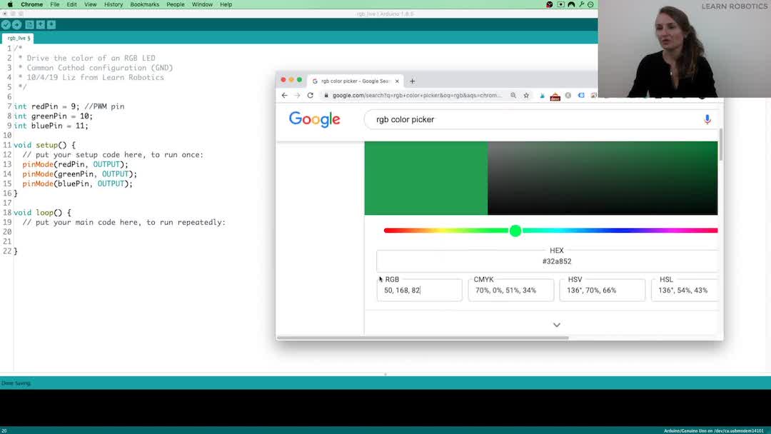
Play around with the slider wheel and select a color. The closer you are to the red, green, or blue colors, directly, the better the color is going to look on the LED.
That’s based on resolution and also how our eyes interpret colors, but for the most part, the purpose of this activity is to show you color mapping, and then using the Hex codes to create RGB LED color patterns.
Once you have a color you like, jot down (or remember) the RGB values. We’ll use these to program the RGB LEDs in just a minute.
Program RGB LEDs with Arduino
The Arduino has an 8-bit PWM output command that we can use to write the Hex values to the signal pins on the LED. It’s called analogWrite(. ) .
Here’s what it looks like:
We’ll repeat this code for each of the colors to create a combination. So, if you wanted to command the RGB LED to red, then you’d use the following lines:
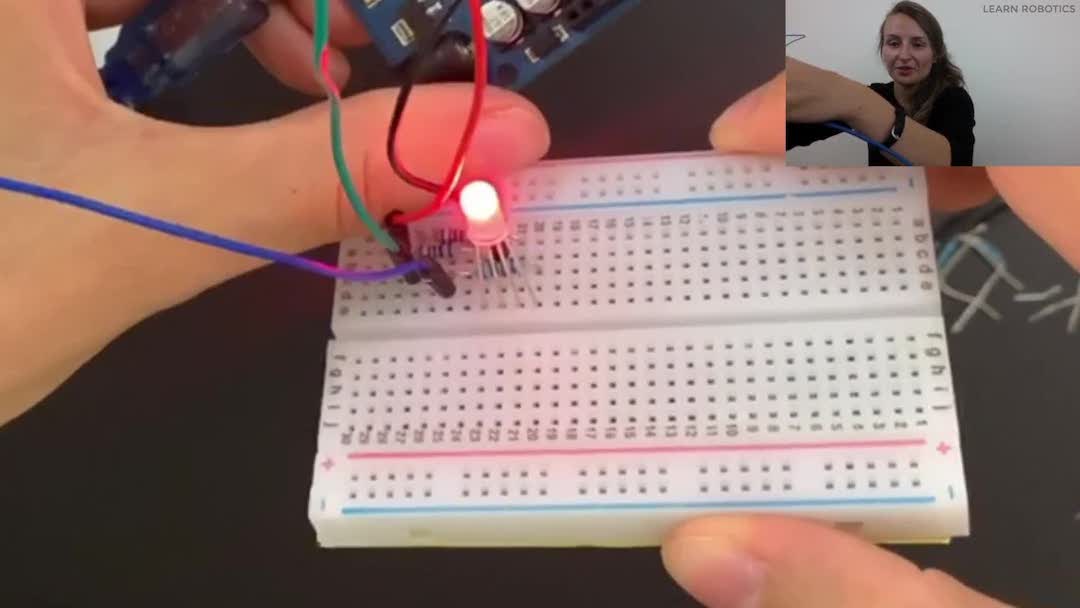
Store these in your method, and upload the code to your board. The LED should be red.
If it’s not, be sure that you’ve assigned the proper pin values to the redPin, greenPin, and bluePin variables. Also, verify that each of the pins is connected to PWM pins on the Arduino.
While it’s pretty easy to command colors, writing those same three lines of code repeatedly can become troublesome. I recommend converting these commands into a method that you can call with input parameters.
Rather than writing a single line to command each color, we can write one line that includes all three values for red, green, and blue. Let’s store this in a method called setColor(. ) .
Then, if we want to set the RGB LED to green, we can use the command as follows:
And that’s it! Call the method in loop() and upload the code to your board.
You can use this method and a for-loop to fade the LED different colors and add delays to control how fast the sequence is.
Combine this project with the random() method to create custom light shows.
Did you try this project? Let me know what you made in the comments below.
You can also watch the full lesson from Special Topics Robotics Course when you enroll in the Free Robotics course.
Support Content Like This
You May Also Like
As Featured In
Have a question? Need Help?
This site uses Akismet to reduce spam. Learn how your comment data is processed.
Give me One Week in your Inbox.
…and I’ll show you the best ways to improve your robotics skills, develop your "engineering mind", and optimize your plan for advancing your career.

I’m Liz Miller, a Robotics Engineer and the brains behind Learn Robotics. I’ve helped hundreds of people build their first robots. Will you be next?
Источник: