


Getting Started with NodeMCU | A Beginner’s Guide
Содержание
- A Brief Lookback at ESP8266
- What is NodeMCU?
- ESP-01 vs. NodeMCU (ESP-12E)
- Layout of NodeMCU ESP-12E Breakout Board
- How to Program NodeMCU using Arduino IDE?
- Conclusion
In this tutorial, we will learn about NodeMCU, ESP-12E Module, layout of the NodeMCU board, a brief pinout and how to program NodeMCU with Arduino IDE. This is a complete beginner’s guide to Getting Started with NodeMCU ESP-12E Board. So, let get started.
A Brief Lookback at ESP8266
The impact of ESP8266 on hobbyist and DIY community, particularly in the development of IoT (Internet of Things) related application is absolutely overwhelming. The ESP8266 SoC is a cheap Wi-Fi Microcontroller with full TCP/IP Stack developed by Espressif Systems.
This is not the first time I am talking about ESP8266 Wi-Fi Module. In fact, I already created a series of projects using the vanilla version of the ESP8266 i.e., the ESP-01 Module.
For more information on Getting Started with ESP8266, its Pinout, firmware and other projects, check out this “15 Best ESP8266 Projects for Beginners”.
The reason for bringing back ESP8266 is NodeMCU. Even though I am late to the party with NodeMCU and its projects, I wanted to create another set of projects starting with this Getting Started with NodeMCU tutorial as more people are buying this board.
What is NodeMCU?
Technically speaking NodeMCU is a firmware for ESP8266 developed using C Programming Language, Espressif NON-OS SDK and Lua scripting language.
Traditionally, we write code for our Microcontrollers like Arduino, STM32, 8051 etc., either in C or C++ and compile it with a set of tools and generate a binary file. This binary file is then uploaded into the flash memory of the microcontroller and it gets executed.
Things are quite different with NodeMCU. You can consider the NodeMCU firmware as an interpreter for Lua Scripts. So, if your ESP8266 is loaded with NodeMCU Firmware, you can simply write your application in Lua and send it to the ESP8266.
NodeMCU Firmware will interpret the bytecode and executes the commands. There is no compilation, no binary file etc. Just write a script and run it.
The team which developed NodeMCU Firmware also developed a breakout board for ESP-12E module called the NodeMCU Devkit. So, many of us are actually using the board called NodeMCU and programming it with Arduino IDE and not the Lua Scripts.
IMPORTANT NOTE: Only one firmware can exist on the ESP8266. It can be either AT Commands Firmware, NodeMCU Firmware or Arduino based code. Once you upload an Arduino sketch, the NodeMCU firmware gets erased. If you want to work with Lua Scripts and NodeMCU, then you have to flash the NodeMCU Firmware.
ESP-01 vs. NodeMCU (ESP-12E)
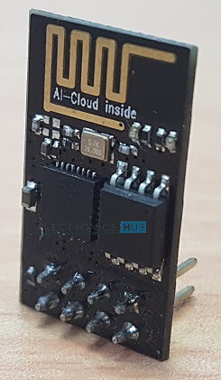
As mentioned earlier, the NodeMCU Devkit is actually a Breakout Board for the ESP-12E Module. The ESP-01 is the vanilla version of the ESP8266 Wi-Fi SoC made by Ai–Thinker, a third part module manufacturer for ESP8266.
In fact, the modules produced by Ai–Thinker are one of the widely used in other ESP8266 boards. Some of the modules from Ai–Thinker are ESP-01, ESP-02, ESP-03, and so on up to ESP-14.
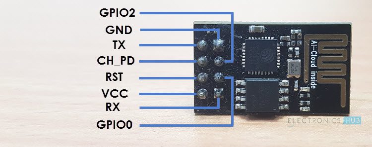
NOTE: All modules are based on the same ESP8266 Wi-Fi Chip. The main difference is the availability of GPIO Pins. For example, the ESP-01 Module has only 2 GPIO Pins whereas the ESP-12E Module has 17 GPIO Pins, ADC Pin, SPI Pins etc.
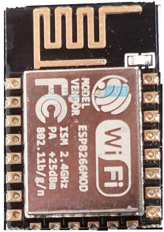
Out of all these modules, the ESP-12E is quite popular. Using this module as the main board, the NodeMCU team developed the NodeMCU Devkit, which is often simply called as the NodeMCU Board.
If you remember the “Getting Started with ESP8266” tutorial, we had to go through a lot of trouble in order to program the ESP-01 Module. It needs an USB to UART Module, some push buttons to switch between Programming mode (GPIO 0 must be connected to GND) and Normal Operation Mode (GPIO 0 can be left floating or can be pulled high to 3.3V).
The NodeMCU board simplifies all this. First, since it is based on ESP-12E Module, there are a lot of GPIO Pins. Second, there is an on-board 3.3V regulator (remember, the ESP8266EX SoC works on 3.3V and not on 5V).
Another beautiful thing about NodeMCU is its inclusion of on-board USB to UART Controller, which is CP2102 IC in my case. An interesting thing about this CP2102 IC is that the GPIO 0 and RST pins of the ESP8266 SoC are controlled by the DTR (Data Terminal Ready) and RTS (Request to Send) pins of the CP2102 IC.
So, when ever you try to upload any sketch from Arduino IDE, the CP2102 IC will automatically select the Programming mode and also Resets the board. Once the programming is done, it configures the ESP8266 back to Normal Running mode. Beautiful.

The official github page of NodeMCU is here.
Layout of NodeMCU ESP-12E Breakout Board
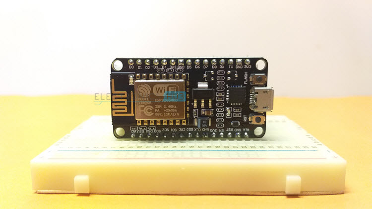
The following image shows the layout of NodeMCU Board, a breakout board based on ESP-12E Module. The ESP-12E Module consists of edge castellations, making it easy to solder on to a PCB.
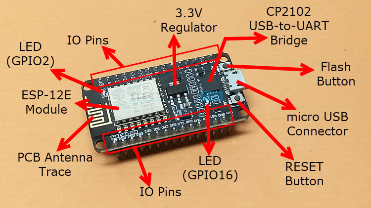
As you can see in the image, the NodeMCU board consists of 30 Pins (15 on each side), an ESP-12E Module with PCB Antenna, CP2102 USB to UART Bridge Controller from Silicon Labs, two push buttons (one is RESET and the other is Flash), a micro–USB Connector for Power and Uploading, a 3.3V Regulator, some passive and active components and two LEDS.
Yes. The NodeMCU has two on-board LEDs. The first LED comes with the ESP-12E Module and is connected to GPIO 2 of ESP8266 SoC. The second LED is on the break-out board (near the CP2102 IC) and is connected to GPIO 16.
NOTE: Both the LEDs are active LOW, which means, when the pins are LOW, the LEDs are ON and when the pins are HIGH, the LEDs are OFF.
Pinout
I will show a brief pinout of the NodeMCU ESP-12E Breakout board. In a separate tutorial, I will discuss the complete pinout of NodeMCU Board, the ESP-12E Module, the pin description and other important features.
The following image shows the pinout of NodeMCU Board.

How to Program NodeMCU using Arduino IDE?
The Getting Started with NodeMCU is not complete until you upload the Blinky Sketch using Arduino IDE. So, let us proceed with configuring Arduino IDE. If you worked on ESP-01 Module or other ESP8266 based boards, the you probably completed the initial setup in Arduino IDE.
Preparing Arduino IDE
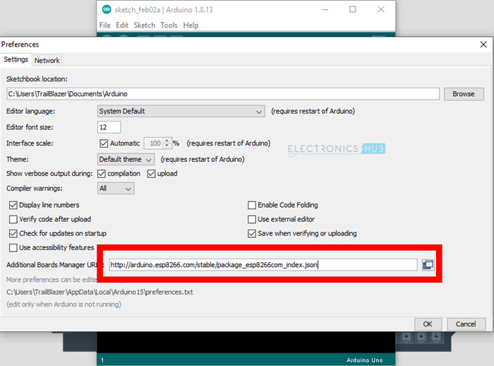
But none the less, let me explain the steps once again. Open the Arduino IDE (if Arduino IDE is not installed, well, install it first) and go to File — Preferences .
There is section called “Additional Boards Manager URLs:” at the bottom. Paste the following URL in the field next to this.
If you want to add multiple URLs, then simply separate them by comma.
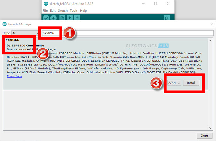
What this does is it allows Arduino IDE to look for additional boards from the internet. So, make sure your system is connected to internet. Now, go to Tools — Board — Boards Manager. . . option.
Using the search field at the top, search for “ esp8266 ”. You will get a result as “esp8266 by ESP8266 Community”. Select this and click on install. It will download all the tools, libraries, boards etc.
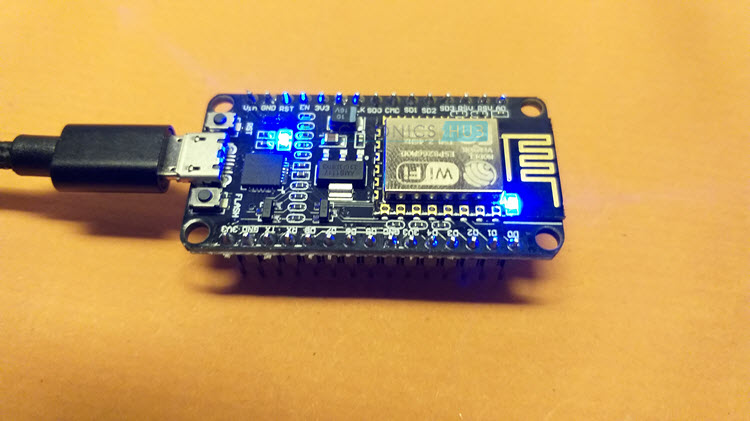
After installing the ESP8266 boards, you can start writing code for your new NodeMCU board. First, connect the micro-USB cable to the NodeMCU and plug-in the other side of the cable to the computer.
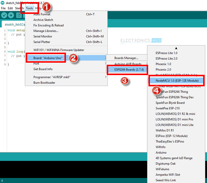
Now, once again go to Tools — Board — ESP8266 Boards in the Arduino IDE and select “ NodeMCU 1.0 ESP-12E Module ”.
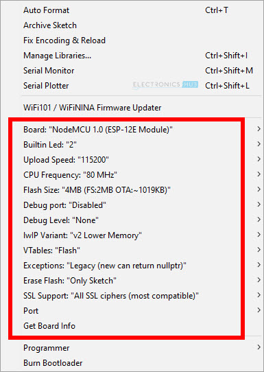
If you click on Tools option in the IDE, all the board related options are changed and are specific to ESP8266 NodeMCU. Leave all the settings to their default except the Port. Select the appropriate port for the USB to UART Controller. In Windows, you can get this information from “Device Manager”.
Testing with Blinky Sketch
As I mentioned earlier, the NodeMCU has two on-board LEDs connected to GPIO 2 and GPIO 16 respectively. So, in this example Blinky Sketch for NodeMCU, I will blink both the LEDs alternatively.
The code for Blinking LEDs on NodeMCU is given below.
Once you click on the Upload button, the Arduino IDE will invoke some ESP8266 related tools to compile the code and generate the binary file.
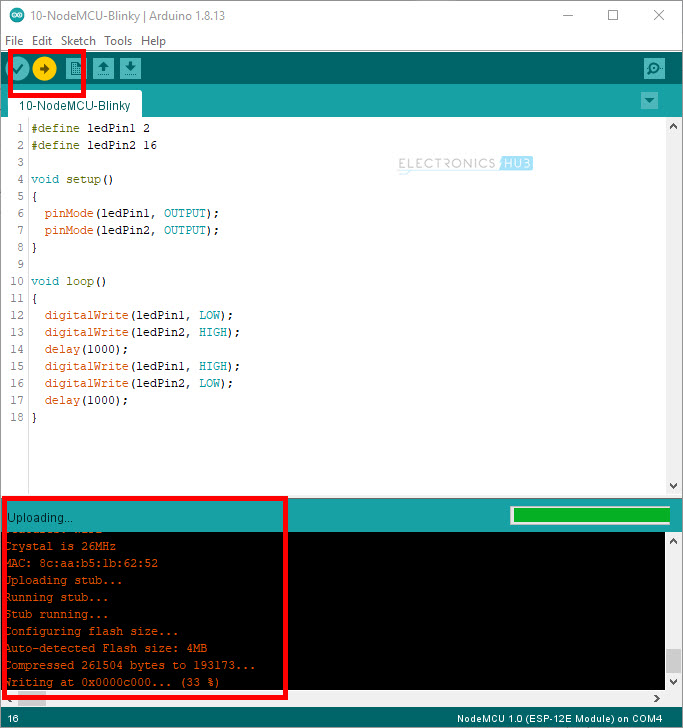
Following is short video snippet of the output.
Conclusion
A complete Beginner’s guide to Getting Started with NodeMCU. NodeMCU is a great version of ESP8266 SoC as it has all the bells and whistles you require in order to build a complete system. In the coming tutorial, I will implement some more beginner as well as advanced projects using this NodeMCU Board. So, stay tuned.
Источник: