


Ublox NEO-6M GPS Module
Содержание

The NEO-6M GPS module is a well-performing complete GPS receiver with a built-in 25 x 25 x 4mm ceramic antenna, which provides a strong satellite search capability. With the power and signal indicators, you can monitor the status of the module. Thanks to the data backup battery, the module can save the data when the main power is shut down accidentally. Its 3mm mounting holes can ensure easy assembly on your aircraft, which thus can fly steadily at a fixed position, return to Home automatically, and automatic waypoint flying, etc. Or you can apply it on your smart robot car for automatic returning or heading to a certain destination, making it a real "smart" bot!
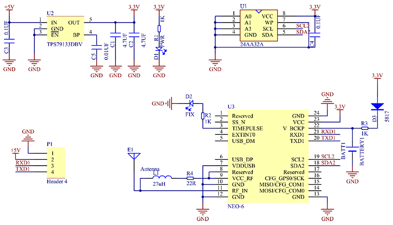
The schematic diagram of the module is shown as below:
Features
1) A complete GPS module with an active antenna integrated, and a built-in EEPROM to save configuration parameter data.
2) Built-in 25 x 25 x 4mm ceramic active antenna provides strong satellite search capability.
3) Equipped with power and signal indicator lights and data backup battery.
4) Power supply: 3-5V; Default baud rate: 9600bps.
5) Interface: RS232 TTL
Test
In this test, we will send the positioning data collected by the NEO-6M GPS Module to the software on the PC, and compare this result with that of a standard GPS device. Thus we can know whether this module works or not.
Preparations
1 x USB-to-Serial Module (e.g. FTDI Module)
1 x USB Cable
Laptop
1 x NEO-6M GPS Module
Note Pay attention to the wiring between the power and ground of the testing board, like VCC and GND, to prevent a short circuit.

Procedures
1) Connect the NEO-6M GPS Module and the FTDI Module as shown below.
| NEO-6M GPS Module | FTDI Module |
|---|---|
| TX | RX |
| RX | TX |
| VCC | VCC |
| GND | GND |
2) Then connect the FTDI Module to the computer with a USB cable. Observe and you’ll see the red LED blinking, then take the GPS Module outdoor (move them all to a position where the GPS module can receive the signal from satellites).
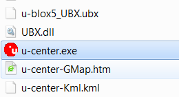
3) Download u-center.zip to your computer and unzip it, and then double-click to run u-center.exe.
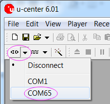
4) Select the correct COM port to connect in the software as shown below:
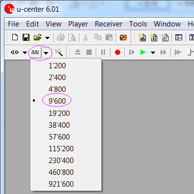
5) Select 9600bps for the baud rate as shown below:
6) If the GPS Module works, the green indicator on the module will blink, and the figures as about the time, latitude, longitude etc., will be shown in the software.
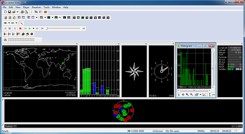
In the end, compare the figures shown in the software with the data collected by a standard GPS device. If the figures are the same, then the GPS Module passes the test.
Источник: