


Microchip direct
In addition to making Nixie and VFD display tubes, the Reflektor factory in Saratov, Russia built clocks for use in office buildings and other large spaces such as Moscow Metro stations. These were produced under the Elektronika 1 7 (Электроника 2 7) name. These clocks have a bit of a cult following in the West and were described by Brian Stuckey of TubeClockDB as being “so unique it has its own Wikipedia entry”. While the English Wikipedia article is a rather small orphan article, the Russian Wikipedia has far more information here and here.
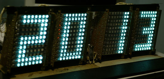
The Elektronika 7 isn’t a single model of clock, but instead is a whole series of clocks of different sizes and functions. The one discussed in this article is the “baby” Elektronika 7-06M. It uses 16 IV-26 Type 3 (ИВ-26 тип 3) VFD tubes, each with 7 dots, arranged as 4 groups of 4 tubes, one for each digit. An IV-6 (ИВ-6) seven segment tube 3 serves as the separator between the hours and minutes. The clock is 15″ wide x 7″ high x 2.75″ deep. Each digit is approximately 2″ wide x 3.25″ high.
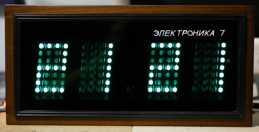
It is actually quite difficult to get a good picture of an assembled and operating Elektronika 7 due to the highly reflective nature of the glass and the high contrast between the lit dots and the rest of the clock. Digital cameras also have a different color response than the human eye, and the combination of the green-tinged blue of the bare VFDs combined with the green glass makes for a particularly challenging subject. The above picture is a best approximation of the actual appearance and is the result of an actual photograph manipulated in Photoshop. The thin vertical lines adjacent to illuminated dots are caused by the light from the dot reflecting off the glass envelope of the adjacent tube(s).
Here’s a video of the clock during the transition from 23:59 to 00:00. Being a Soviet clock, it only displays in 24 hour mode.
(Click the icon on the top right to go fullscreen.)
Both this video and the photograph above it were shot in “dim” display mode after the tubes had been replaced (see the restoration section later in this article). The still photo has a much more accurate rendition of the display color when viewed through the green front panel glass.
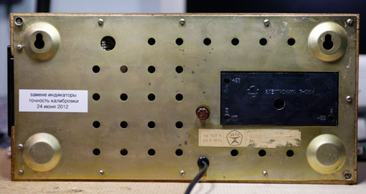
Here’s a view of the back of the clock after I completed my restoration project. The sticker on the right is the original manufacturer / date / serial number sticker, which was defaced at some time in the past (more information later in this article). Above that is the battery compartment door for the backup timekeeping batteries. There are 3 test points on 3 corners of the battery compartment, two for checking the battery voltage and one for (roughly) checking the timekeeping accuracy. Directly above the power cord is a .25A fuse. On the left side I have placed a label indicating that I replaced the tubes and calibrated the clock, along with the date.
In addition to the 7-06M model described in this article, other versions were manufactured with larger displays. I have one with a label reading 7-06 (no suffix) dated 1984 which uses 12 horizontal tubes per digit. I have photographs of one labeled 7-06K dated 1989 which has 11 tubes per digit. This may have been a reduction for cost reasons more research is needed.
These clocks were manufactured between (at least) 1982 and 1991. The oldest clock I’ve seen has a 1982 date, while the instruction manual (which was supplied with a clock, as it has a serial number written on it) is dated 1991. Production may have started before 1982 or ended after 1991.
The Russian Wikipedia article referenced above states that the clocks were introduced in 1982 and that the K model suffix indicates that the clocks were equipped with a connector for radio synchronization of the time. However, my 7-06 (no K) also has this connector.
Modern versions of the Elektronika clocks are still being manufactured in Russia under the Vesta name. These are available with red or green LEDs or the more traditional VFD (but not with IV-26 tubes, which are no longer manufactured). This is apparently what the soda-can-sized ILC1-1/7 (ИЛЦ1-1/7) 7-segment displays are used for there is a YouTube video of a 6-digit one in operation here.
Operation
Operation of the clock is quite simple. After plugging it in, the clock will display 00 00 (unless backup batteries were installed, in which case it should retain the correct time) and the colon indicator will be flashing once per second. There is a vertical row of buttons on the right side of the clock case. Refer to the following image for the functions of each button:

- МИН Minutes Press and hold to increment count 2 times per second, or press once to increment once
- ЧАС Hours Press and hold to increment count 2 times per second, or press once to increment once
- СТОП Stop Reset minutes and seconds to 0 and stop counting until released (latching button)
- ЯРК Bright Dim display while pressed (latching button)
Setting the time involves pressing ЧАС to set the hours, pressing СТОП until your reference time shows 00 seconds and then releasing, and then pressing МИН to set the minutes. Changing the hours or minutes does not affect the (internal) seconds counter.
I obtained an instruction manual from WASP in Kazakhstan. With their permission 4 , the manual is available for download from my site here (PDF, 16MB).
Internal construction
The internal components are all mounted to a metal frame which has 4 metal “ears” which are attached to the cabinet with screws. Refer to this numbered picture to identify each major component:
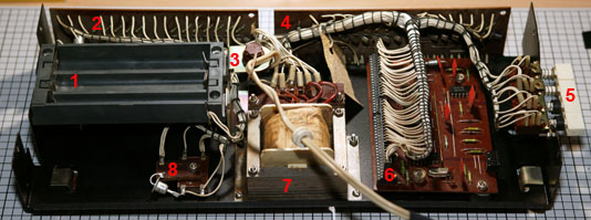
Clockwise from the left side, the components are:
- Compartment for 6 Type 316 (AA equivalent) batteries for timekeeping (but not display) during power outages
- Hours decode / display circuit board
- 1/4A input power fuse
- Colon and minutes decode / display circuit board
- Buttons for setting time and dimming display
- Logic board
- Input power transformer (220V input; 23V and 3.2V outputs)
- KC402E (КЦ402Е) full-wave bridge rectifier (right) and D226 (Д226) diode (left)
Note the use of connectors on the logic board. I have seen clocks of this model which also use connectors on the two display boards, which was apparently done to make it easier to service the display boards. Strangely, this seems to have been discontinued. My clock has a late 1988 date code, white wires with black lacing cord, and no connectors on the display boards. Another clock of the same model has a mid 1986 date code, green wires with white lacing cord, and connectors on the display boards. The service manual the schematics came from is dated April 1991 and doesn’t show the connectors.
While getting ready to clean the circuit boards, I removed the inspection sticker that was tied to the wiring harness on the minutes board, shown just to the right of the “4” legend in the above picture. It has an odd mixture of dimples (both in and out), rubber stamp, and handwritten markings in both pen and pencil:
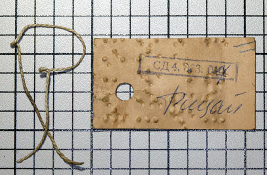
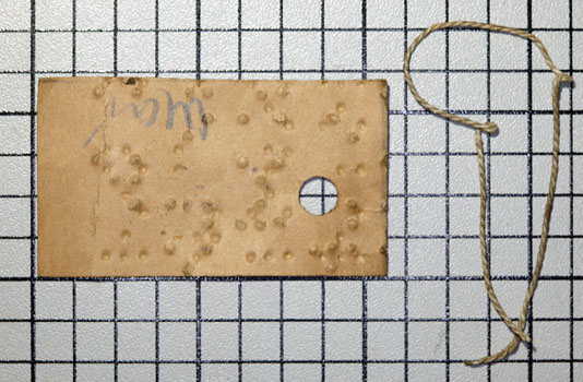
Eremeev Alexey wrote in to say: “I have just little note about “inspection sticker that was tied to the wiring harness…………. It has an odd mixture of dimples” actually its not odd dimples, it iss recycled paper from old books for blind people (Braille writing system). Suspect so it was because many disabled people work (often work in Soviet Union time) on electromechanical plants and they assembled more or less simple devices such wall sockets and switches. Such job may had in nearby worskhop in factory and they may had lots of useless braille paper documents.”
Display
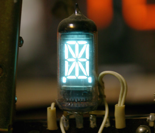
As mentioned above, the clock uses IV-26 tubes for the display:

IV-26 tubes were manufactured in 3 variants. The Type 1 has individually-addressable dots while Type 2 has internal connections between dots 1-2, 3-5, and 6-7. Type 3 has internal connections between dots 2-3 and 5-6. Type 2 was used to create numeric displays from horizontal tubes and Type 3 was used to create numeric displays from vertical tubes. This was presumably done to reduce the amount of assembly labor, as a clock with 16 Type 1 tubes would have 144 soldered connections, while a clock with 16 Type 3 tubes would only need 112 soldered connections. That isn’t a huge savings, but on the 12-tube-per-digit 7-06 version (to be discussed in a later article) the connection count drops from 432 to 240. (The percentage saved varies because a Type 3 tube has 7 pins while a Type 2 tube only has 5 pins.)
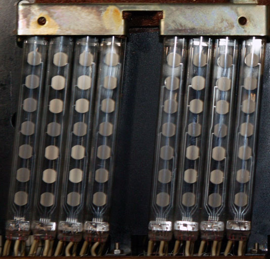
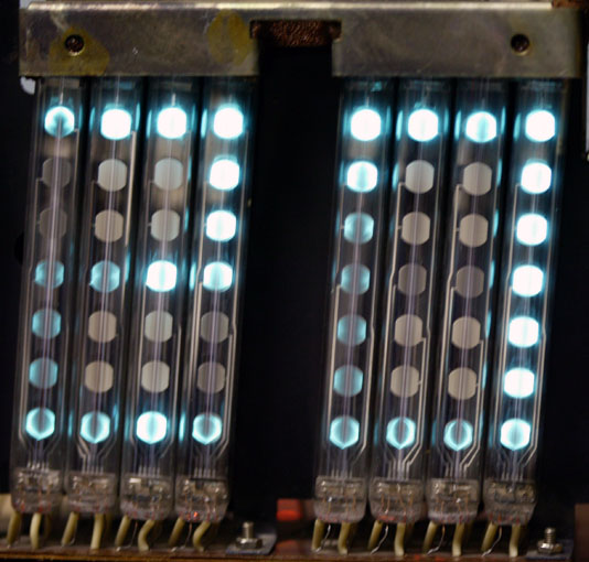
After operating for over 20 years, the various dots within the tubes have faded from use. This varies depending on how often a particular dot is illuminated, and the fading of the dot is accompanied by a darkening of the phosphor material. This does not correspond exactly to the fading of the dot as you can see in the following two pictures of the same tubes when off and lit:
Circuitry
Given the somewhat bizarre use of IV-26 tubes to create a pseudo-seven-segment display, I assumed that the circuitry would be equally Byzantine. It is actually very elegant. The same circuit board is used in multiple clock models, since the timekeeping is separate from the display decoding and drive. It has features not used in the 7-06M for example, connectors for a daughterboard to process an external radio synchronization signal.
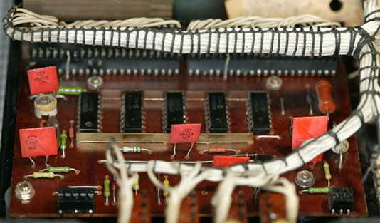
The circuit board contains 6 integrated circuits which operate at 9V (not standard 5V TTL levels). They are:
- K176IE12 (К176ИЕ12) 15-bit frequency divider with 1PPS and 1PPM outputs
- K176IE4 (К176ИЕ4) Modulo 10 counter with 7-segment output (2)
- K176IE3 (К176ИЕ3) Modulo 6 counter with 7-segment output (2)
- K176LA7 (К176ЛА7) Quad 2-input NAND gate
The timebase is generated by a 32KHz RK-72 (РК-72) crystal, known colloquially as a “boat crystal” due to its shape. A trimmer cap provides adjustment of the frequency for accurate timekeeping.
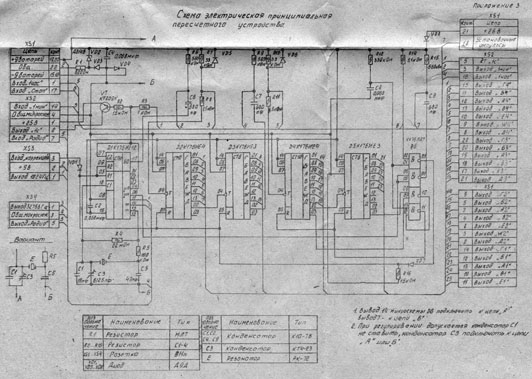
[Click on the schematic for a full-size version.]
The display boards use a series of KT209 (КТ209) PNP transistors to switch the 25V drive to the tube dots on and off, controlled by the 9V logic levels from the main logic PCB. The 1’s of hours and 1’s of minutes each use 7 transistors, one for each of the emulated 7-segment display elements. The 10’s of hours only uses 5 transistors as this digit only needs to display 0, 1, or 2. The 10’s of minutes uses 6 transistors as the possible digits are 0 through 5. There’s a bit of a clever trick with four diodes on the leftmost tube on the 1’s of hours and both minutes to complete the 7-segment decoding. The 7-segment tube used as the colon display receives its voltage from a KT209 transistor located on the main logic PCB. I’m not sure why this was done there is certainly enough room on the minutes display board for an additional transistor. Refer to the complete schematic set (PDF, 13MB) for additional information.

Power
Since this clock comes from Russia, it operates on 220V 50Hz power. Fortunately, it doesn’t rely on the AC line frequency for timekeeping so the 60Hz power in the US is not a problem. However, it does require 220V and won’t work on regular wall power here. For testing, I have a Goldsource STU-300 (Amazon link) power converter. This is a true transformer-based voltage converter and not a simple adapter plug (which wouldn’t work). 300 Watts is massive overkill for this clock (the manual says it consumes 20W). However, this is a nice adapter to have around as it has a regular US 5-15P plug on it and has universal receptacles on the front.
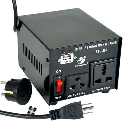
[Stock photo from amazon.com]
After I finished restoring the clock, I plugged it into a large Symmetra UPS I have in my server room. That UPS has 220V outputs as well as the normal 120V ones.
Restoration
As I mentioned above, the tubes had become dim with age and for the best appearance I decided to replace them with NOS (new old stock) tubes. I used the same Type 3 tubes that were used originally in order to keep the wiring identical, and I also re-used the original insulating sleeves. There were strips of orange-brown open cell foam which were used along the tops of the IV-26 tubes to prevent damage during shipment. Like most foam from that era, it had denegerated into a sticky goo that would not spring back once pressed. The same foam was used on the inside of the battery compartment cover. I replaced all of this with a modern grey open cell foam trimmed to the same dimensions, after cleaning off the residual goop from the frame. Since I was replacing all 16 IV-26 tubes, I decided to replace the IV-6 colon tube for completeness. I was concerned that while it originally looked fine, it would appear dim when contrasted with the new IV-26 tubes. While the tubes were removed, I carefully cleaned the black metal plate behind them.
I decided to replace the tubes 8 at a time (one board’s worth). In addition to giving me a good reference for what the positioning should be, this also allowed me to take the following photograph, which shows just how badly the tubes had deteriorated over 20+ years of operation:
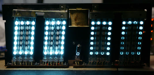
I noted with interest that both the original IV-26 tubes and the replacements I installed were manufactured by Orzep, not Reflektor, despite the two companies being competitors (or at least as much as there was competition in the Soviet system). Both the original IV-6 colon tube and its replacement were manufactured by Reflektor. A search on eBay (which certainly isn’t definitive) doesn’t show any IV-26 tubes made by Reflektor. In all cases where a logo is visible, it is the Orzep logo. Perhaps Reflektor never manufactured the IV-26 tube type.
If you decide to replace the tubes on your own Elektronika, be very careful as the circuit traces can de-laminate from the PCB. Use the lowest wattage soldering iron and the minimum temperature that will do the job. When inserting the tube pins, watch out for the pins getting stuck on the circuit pads and trying to lift them off the board.
I also blew all of the loose dust out of the internal components. As I worked on each board, I carefully cleaned it with board cleaning fluid and an assortment of hog bristle brushes to dislodge any debris that remained on the board after cleaning with the compressed gas duster.
Next, I used contact cleaning spray to clean the switches that protrude through the side of the case. I also wiped down the buttons with an alcohol pad to remove decades of cigarette smoke, grime, and other things I don’t want to think about that were deposited on the buttons over the years.
Having completed the innards, I turned my attention to the case. My first step was to use a spray on wood cleanser / polish to remove the decades of built-up gunk. After several coats and buffing the wood to a nice finish, I moved on to the inside of the case. Again, I used the duster to blow loose material out of the inside. I gave the interior wood a quick wipe to remove some more of the dust, but concentrated most of my efforts on the front glass 5 . Using a streak-free cleanser I removed an amazing amount of grime from the inside of the glass. If you do this on your own Elektronika, please use caution as the black paint mask on the inside of the glass is relatively fragile. You don’t want to either dissolve or chip it. I then repeated the glass cleaning on the outside. The caution about being gentle applies doubly here the Электроника 7 lettering on the front is also quite fragile. Once I had a perfect streak-free glass, I cleaned the plastic surround with alcohol wipes and cotton swabs to get into the crevices and seams.
The bezel for the control buttons had been removed as part of the procedure for extracting the internal frame from the case. It received the same alcohol cleaning that had been used on the buttons and the display surround.
The remaining case components were the rear metal panel and the battery box cover. These received a quick wipe-down to remove any surface crud, being careful to not damage the serial number / warning sticker any further (the model and serial information had been defaced at some time in the past, presumably to keep the source of the clock secret if it was found in an unauthorized location).
My last step was to replace the taped-on power extension cord with a 2-wire Europlug cord. As these clocks were designed to hang on walls, the orginal power cords were probably quite short I’ve never seen one with an original cord longer than a foot or two. Normally the people who salvaged the clocks would attach a power cord to the original cord, using varying levels of skill and safety. When this particular clock was delivered to me, it had an original 1 foot power cord and another 10 feet of power cord attached with electrical tape. There was no plug on the end, though, just some bare wires hanging out. This needed to be cleaned up for both safety and aesthetic reasons.
I wasn’t able to locate a new power cord with an attached plug in the same off-white color that was originally on the clock. However, I did find a nice 6′ 2-wire Europlug cord in black, in the same flat style as the original cord (most power cords these days are round). It is a model 10W1-13306 (Amazon link), intended for use with notebook computers. A quick removal of the receptacle and some soldering gave me a nice new power cord for the clock. While this isn’t the exact same type of plug that was used in the Soviet Union, it still allows the clock to be plugged into a Russian outlet and operate.
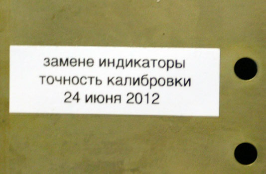
After all this, I felt that the clock deserved a label indicating that it had been restored to as-new condition, so I made one up (in Russian, of course) and attached it on the left side of the back panel:
Timekeeping accuracy
As received, the clock gained about 2 seconds per day. I mentioned earlier that the timing source is a 32KHz crystal and adjustable capacitor. These were never terribly accurate, and this clock is well over 20 years old and has probably never been adjusted since it left the factory.
I used a frequency counter to adjust the timing with the capacitor. I had some concern that the capacitor would fail during the adjustment due to dust or other stuff getting between its plates. I’ll monitor its accuracy over the next month or so, and if it still gains or loses time (particularly with changes in temperature), I’ll probably design a board to plug into the clock’s unused external timing input. A DS32KHZ temperature compensated timing IC will provide a clock with an accuracy of 1 minute per year (better than .16 seconds / day).
Teaser
Look for an upcoming article on this clock’s big brother, the 48-tube Elektronika 7-06:
Footnotes
[1] Pronounced ee-lec-TRON-ee-kuh. Not uh-lec-… or eh-lec… [2] Each time I first reference a Russian part number, I enclose the Cyrillic spelling in parenthesis. This is mainly to help search engines locate this page. [3] The colon tube is actually an IV-6, not an IV-8. This has been confirmed on both my clock and the schematics the Russian Wikipedia article is wrong. [4] The WASP site states “I don’t mind when my articles are used on other web resources [in] the Internet community, certainly an indication of the author and links to my site are very welcome. The use of my material in the paper press or advertising material is different and requires permission from the author write [to me], [as I] reply to all [inquiries].” [5] An original Elektronika 7-06M will have a sheet of green glass (not plastic) with black paint on the inside to mask out everything but the tubes. If you see an Elektronika 7-06M with plastic or clear glass, it has been modified at some point in the past. The same is true of most other Elektronika 7 models, though some were built with MTH90 (МТХ90) thyratron displays which would need an orange filter.My goal is for this blog to be the most complete source of information about the Elektronika 7 in any language. I welcome comments / suggestions on how to improve this article.
This entry was posted on Sunday, June 17th, 2012 at 12:52 am and is filed under Clocks. You can follow any responses to this entry through the RSS 2.0 feed. You can skip to the end and leave a response. Pinging is currently not allowed.
4 Responses to “ The Elektronika 7-06M Clock ”
In this blog entry, I said I wasn’t sure why the colon tube’s 26V drive signal was generated on the main logic board instead of one of the display boards. The reason for this is that the same main logic board is used in the larger versions of the clock, where each digit has its own display board. The colon tube on those clocks is wired directly to the main logic board there’s no separate board for it, just a 6-pin terminal strip:
Incorporating the colon tube’s drive circuitry on the main logic board allows the same logic board to be used in multiple versions of the clock.
Just to let you know that there are some grammatical errors in what you’ve written in Russian. It should say:
Заменены индикаторы
Точность проверена
@Epaulard thanks for the correction. I rely on being able to recognize a few technical terms, but I use a number of online resources for the other translation tasks. When I make up the next batch of labels, I’ll use your corrected text on them. Thanks!
HI
Where can i buy K176IE4 Counter?
I need it for my russian geiger counter.
Thank you.
Источник: