


MCUFRIEND 2.4” TFT Display
Содержание
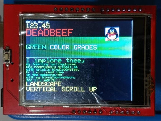
This note introduces a low-cost Thin Film Transistor (TFT) display to enhance the operation and usefulness of Liquid Crystal Display (LCD).
Things used in this project
Hardware components
Software apps and online services
Story
This note introduces a low-cost Thin Film Transistor (TFT) display to enhance the operation and usefulness of Liquid Crystal Display(LCD) devices. TFT technology controls the pixel element on the glass surface thereby greatly reducing image blurring and improving viewing angles.
The test board chosen for this exercise is the Elegoo Arduino UNO board from the corresponding Super Starter Kit. The kit already has several simple numeric and text displays. The TFT display may perhaps provide better ways to interact in applications.
The key specifications of the display are:
Diagonal Screen Size 2.4 inch
Display Resolution 240 (RGB) x 320
Viewing Angle 6 o’clock
Interface Type MCU parallel or RGB
Brightness 220 cd/m2
LCD Driver IC Ilitek ILI9341
Module Size (w x h) 42.72 x 59.46 mm
Active Area (w x h) 36.72 x 48.96 mm
Pixel Size 0.153 x 0.153 mm
Operating Temperature -20
The controller for the illustrated model of the TFT display is SSD1297.This information is important because the display (owing to its low cost and high popularity) has many different manufacturers who may not leverage the same controller instruction set. The specification of the controller in the coding exercises is examined in the Appendix section of this note.
The higher level functions of the library include but not limited to:
- begin
- color565
- drawFastHLine
- drawFastVLine
- drawPixel
- fillRect
- fillScreen
- invertDisplay
- pushCommand
- setAddrWindow
- vertScroll
- setRotation
- readID
- reset
- WriteCmdData

Some familiarity with the coordinate system for displays (i.e. top-left is0, 0) and the packing of RGB values into a 16-bit word (5 for R B, 6 for G) makes the learning curve ramp at a faster pace.
The most fundamental routine to write the specified color at thespecified coordinate location.
Draws a rectangle using the specified color with a top-left cornerfor the starting point and width and height along the respectivecoordinate axes.
Floods the screen with the specified color.
The display mounts as a traditional shield on the UNO board as shown below.
However, without a secondary shield as a sandwich layer, as shown below, access to the pins becomes impractical.
Of course, the display can be mounted elsewhere and the pins connected to the Arduino directly or indirectly using, for example, a breadboard. Other components can then use the breadboard in lieu of a shield with custom connectors. Of course, without access to such anon-standard or readily available breadboard, it is impossible to illustrate this arrangement in this note.
The key pins that much be connected between the display and the Arduino board are:
- Control pins: from A0 to A4
- Data pins: from D2 to D9 touchscreen pins, inapplicable for model under test, vary: A1, A2, D7, D6
The Examples folder for the library provides the starter files for the tests. If you are using a newer display you will need the updated libraries from the GitHub repository (see link in References below)and using the #define statement to identify the display model.
The output from the diagnostic program, LCD_ID_reading.ino, is shown below:
The controller is referenced as SSD1297 with This display requires the use of the following statement in the code prior to the invocation of other header files for the display. Please review the header files for the equivalent
Many thanks to DavidPrentice for the display driver library and the guidance, support and advice during the tests for this display. I would have failed at the starting block without his generous assistance. He is an authority on the drivers for this class of displays.
Источник: