


ESP8266 PWM with Arduino IDE – LED Fading
Содержание
- Prerequisites
- PWM Introduction
- ESP8266 NodeMCU PWM Pins
- Arduino IDE LED Fading Example using PWM
- Conclusion
In this user guide, we will learn to generate PWM or pulse width modulation using ESP8266 NodeMCU board using Arduino IDE. You will see how to generate PWM signals using the ESP8266 NodeMCU development board. All input/output pins of this development board can be used to get the PWM signal. We only need to specify a PIN on which we want to get a PWM signal. Our aim will be to learn how to produce the PWM signals with GPIO pins of the ESP8266 development board and consequently demonstrate a LED fading example.
- We have a similar guide for ESP32 using Arduino IDE as well:
- For ESP8266 ESP32 PWM using MicroPython follow the link below:
Prerequisites
We will use Arduino IDE to program our ESP8266 development boards. Thus, you should have the latest version of Arduino IDE. Additionally, you also need to install the ESP8266 plugin. If your IDE does not have the plugin installed you can visit the link below:
PWM Introduction
PWM means pulse width modulation. It is a type of signal which is obtained from a microcontroller in our case the ESP boards. The output signal is a square waveform which at a particular instance is either high or low. If we are using a 3.3V power supply then the PWM signal would be either high which is 3.3V or low which is 0V. The ‘on time is the duration till which the signal stays high and the ‘off time’ is the duration till which it stays low. In order to better understand the concepts of PWM in our ESP board we need to know about the following two terms which are closely associated with the digital signal
What is Duty Cycle?
Duty cycle is the percentage of time in which the PWM signal is ‘on time’ meaning it remains High. For example if the signal is always OFF it is 0% duty cycle and if it is always ON it is 100% duty signal. The special feature about this is that the user can control the ‘on time’ by controlling the duty cycle. The formula for duty cycle is shown in following expression:
Duty Cycle = ON time of signal / Time period of signal

Different Duty Cycles PWM Signal
The frequency of a PWM signal is the number of cycles per second and it defines how quickly a PWM signal completes one cycle (Period). That means the Period of a PWM signal is the sum of the ON and OFF time of a PWM signal. For example, if the time period of a signal is 20ms, its frequency will be 50Hz where Hz is the unit of frequency. This formula is used to calculate the frequency:
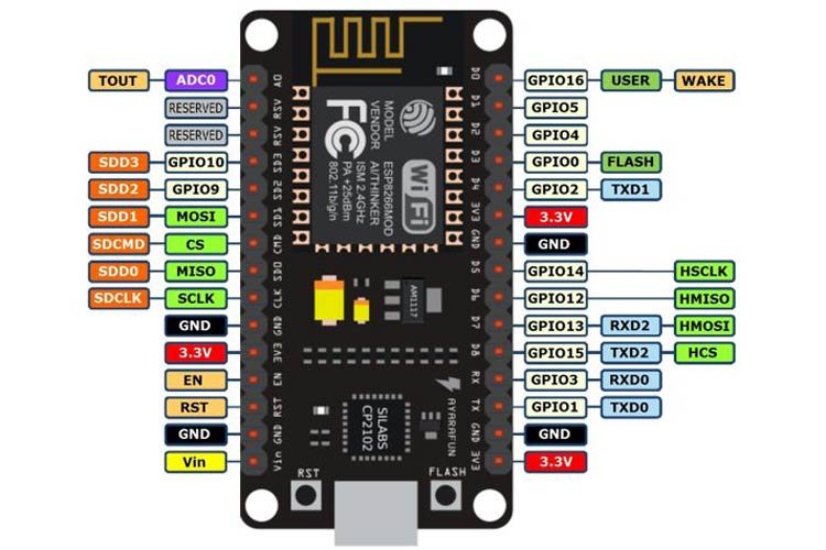
ESP8266 NodeMCU PWM Pins
ESP8266 supports PWM on all general-purpose input-output pins.
| Resolution | 10 bit |
| PWM Supported pins | Input/output GPIO0-GPIO16 |
How to Initialize PWM for ESP8266 in Arduino IDE
By using analogWrite(PWM_Pin, PWM_value) function we will generate PWM in Arduino IDE. This function takes in two parameters. The first is the PWM pin and the second is the PWM value.

- For the PWM pin, we can use GPIO0-GPIO16 in ESP8266.
- For best optimization we work in 8-bit resolution hence the duty cycle will vary from 0-255. So this value can be in the range 0-255 where 0 denotes no PWM and 255 denotes a duty cycle of 100%. If you want to change this range then specify it as a parameter inside the analogWriteRange() function.
- Additionally, the ESP8266 has a default frequency of 1kHz. If you want to change the frequency use, analogWriteFreq() with the frequency value you want to set. The frequency can take values from 100Hz-40kHz.
Arduino IDE LED Fading Example using PWM
Now we will learn how to build a simple circuit that fades the LED according to PWM signals. The following components are required to perform this procedure:
- ESP8266 board
- Breadboard
- One LED
- One 220 ohm resistor
- Connecting Wires
Connection Diagram
We will connect the LED to GPIO13 on ESP8266 board. But you can choose another suitable PWM pin accordingly. Make your circuit connections as shown in the diagram below for ESP8266 below:
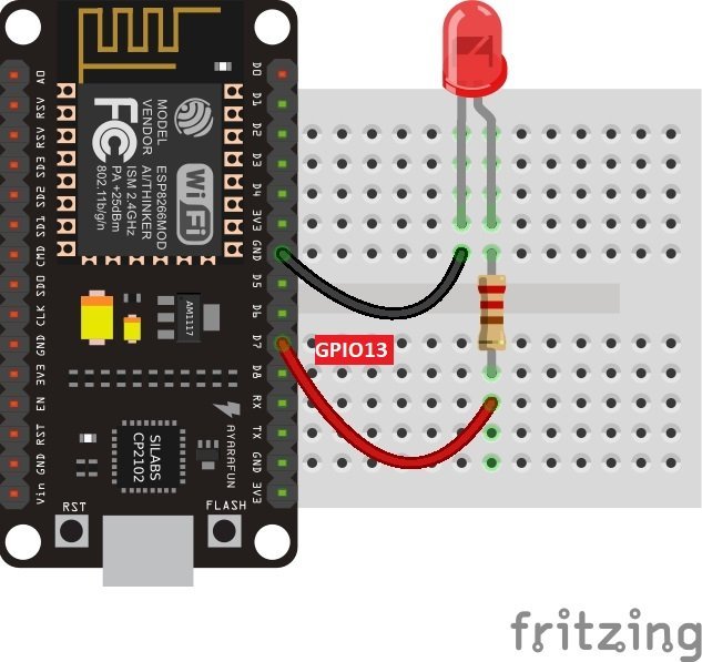
Schematic of ESP8266 for PWM
In the above schematic, we can see that GPIO13 is connected with the anode pin of LED, and the cathode pin is connected with the common ground through the 220-ohm resistor.
Arduino Sketch: ESP8266 PWM LED Fading
We will fade the LED (low to high) by increasing the duty cycle in our program code. To set a PWM signal, we will define these following parameters in the code:
Open your Arduino IDE and go to File New. A new file will open. Copy the code given below in that file and save it. This sketch first brightens the LED by increasing the duty cycle and then fades it by deceasing the duty cycle.
Firstly, we will define the ESP8266 PWM pin that we will connect with the LED. It is GPIO13 in our case. You can use any appropriate PWM pin.
In the infinite loop() function, we will use two for loops to increase/decrease the duty cycle. In the first for loop, we will increment the duty cycle after a delay of every 1ms. The anlogWrite() function will take in the LED pin and the Duty cycle value as the parameters inside it. This will brighten the LED with increasing values from 0-1023.
The second for loop() will fade the LED by decreasing the duty cycle after every 1ms. The anlogWrite() function will take in the LED pin and the Duty cycle value as the parameters inside it. This will fade the LED with decreasing values from 1023-0.
Demonstration
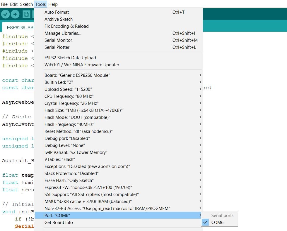
Choose the correct board and COM port before uploading your code to the board. Go to Tools Board and select NodeMCU 1.0

Next, go to Tools Port and select the appropriate port through which your board is connected.
Click on the upload button to upload the code into the ESP8266 development board.
After you have uploaded your code to the development board, press its RST button.
Notice the LED will start getting brighter and than fades as the duty cycle varies over time.

Conclusion
We learned about the PWM module of ESP8266 by increasing/decreasing brightness of the LED by varying the duty cycle over time. Our ESP8266 board was programmed using Arduino IDE.
Источник: