


Esp32
ESP32 is a series of low-cost, low-power system-on-a-chip micro-controllers designed by Espressif in Shanghai, China. It has integrated Wi-Fi and dual-mode Bluetooth radios. It has many of the capabilities of the Arduino and can be programmed with the Arduino IDE software and so is an easy upgrade path to wireless communications for Arduino users.
The ESP32 supports many peripherals such as: capacitive touch, ADC, DAC, I2C, SPI, UART, I2S, PWM. It is appropriate for Internet of Things Projects and enables Bluetooth communications for Smartphone applications.
See Wikipedia: HERE And for LOTS of information, ESP32.net HERE The Espressif Discussion forum is HERE AND See: Neil Kolban’s excellent book and ESP32 Guide
Rui Santos has an excellent ESP32 Education / Project series here: 70+ ESP32 Projects, Tutorials and Guides with Arduino IDE
The ESP32 is an upgrade of the earlier ESP8266 and adds a faster dual-core processor and Bluetooth interface. On the left is a block diagram of the many features inside the ESP32.
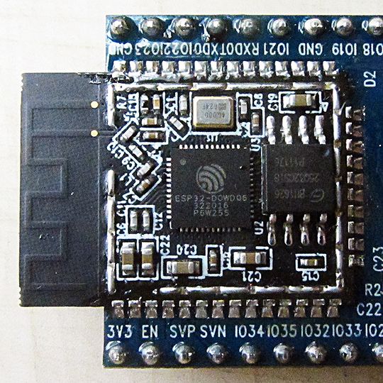
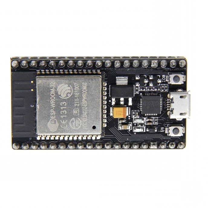
The ESP32 is usually seen as a metal-cased module (In the red rectangle in the section below) that is then placed on slightly larger boards with added components. The metal-cased product includes a crystal oscillator, a flash memory chip. capacitors etc. See the UNcased photo at right. The Metal-cased module has been approved by European and FCC testers. This is a major plus: it can be included in other new products without more testing.
ESP32 Boards we are testing
(Both of these boards have 38 pins on 0.1 inch centers) If you Look-Closely-Now you will see the pinouts are the same.
KS0413 keyestudio ESP32 Core Board
Description
This keyestudio ESP32 core board is a Mini development board based on the ESP-WROOM-32 module. The board has brought out most I/O ports to pin headers of 2.54mm pitch. These provide an easy way of connecting peripherals according to your own needs. When it comes to developing and debugging with the development board, the both side standard pin headers can make your operation more simple and handy. The ESP-WROOM-32 module is the industry’s leading integrated WiFi + Bluetooth solution with less than 10 external components. It integrates antenna switch, RF balun, power amplifiers, low noise amplifiers, filters and power management modules. At the same time, it also integrates with TSMC’s low-power 40nm technology, so that power performance and RF performance are safe and reliable, easy to expand to a variety of applications.
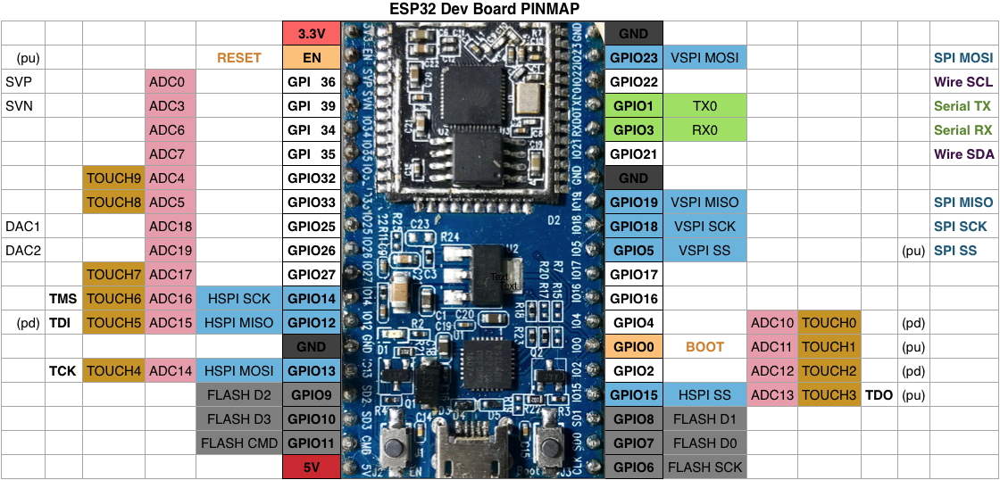
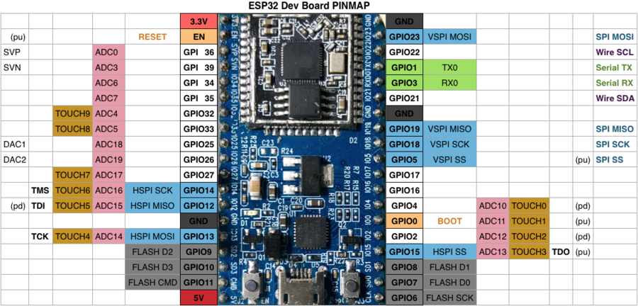
The Pin Map below shows the functions that can be used on each pin.
Technical Details
- Microcontroller: ESP-WROOM-32 module
- USB to Serial Port Chip: CP2102-GMR
- Operating Voltage: DC 5V
- Operating Current: 80mA (average)
- Current Supply: 500mA (Minimum)
- Operating Temperature Range: -40?
— "ESP32 Dev Kit V2"
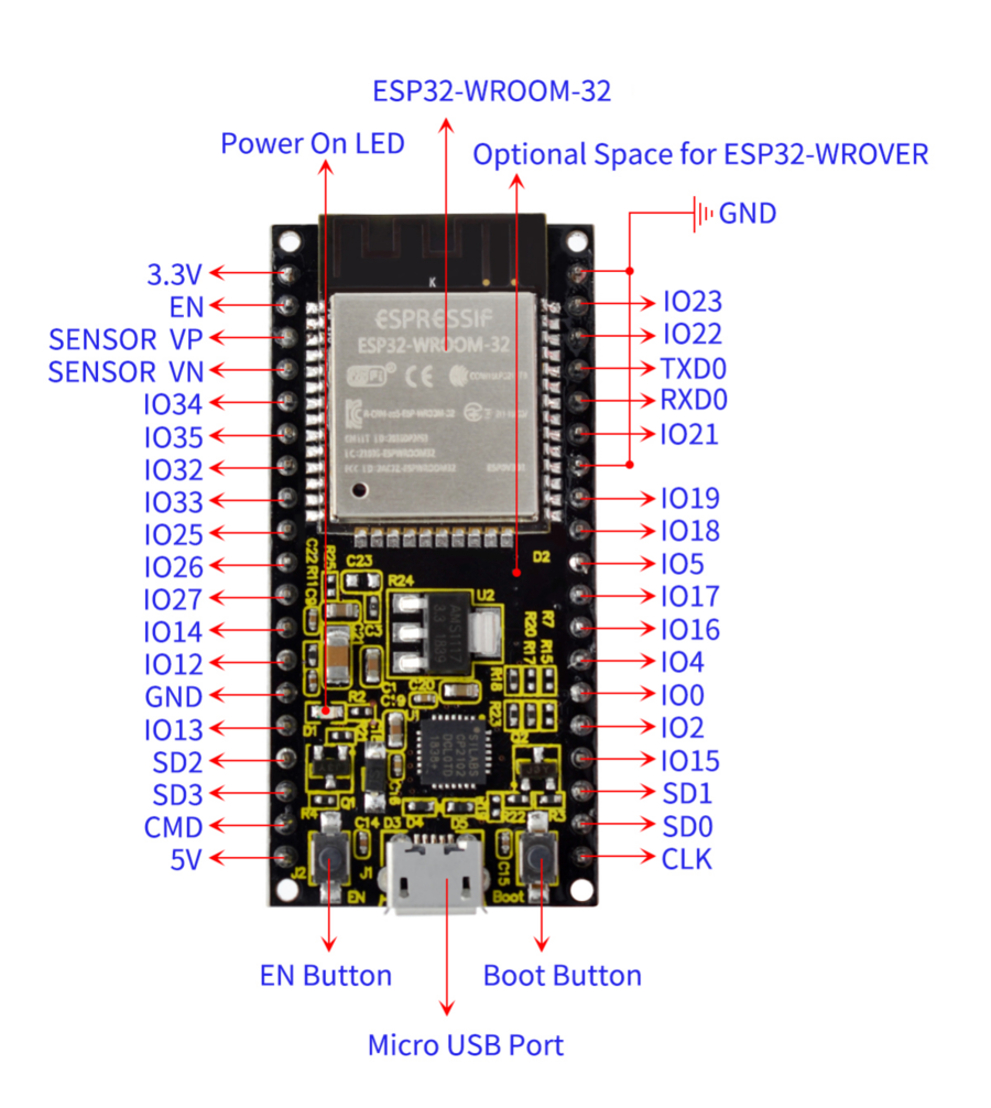
By Espressif, maker of the ESP32 Chips. About $15 Amazon example The pin-out diagram on the right shows the connections to the ESP pins, power, ground etc. Note there are two small pushbuttons labelled BOOT and EN
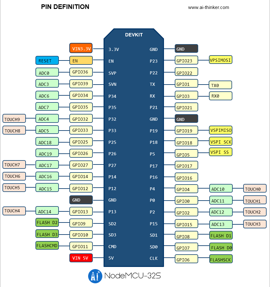
— nodeMCU-32S
By Ai-Thinker. About $12 Amazon ExampleUsually received with firmware called nodeMCU which supports the LUA programming language as well as C++.
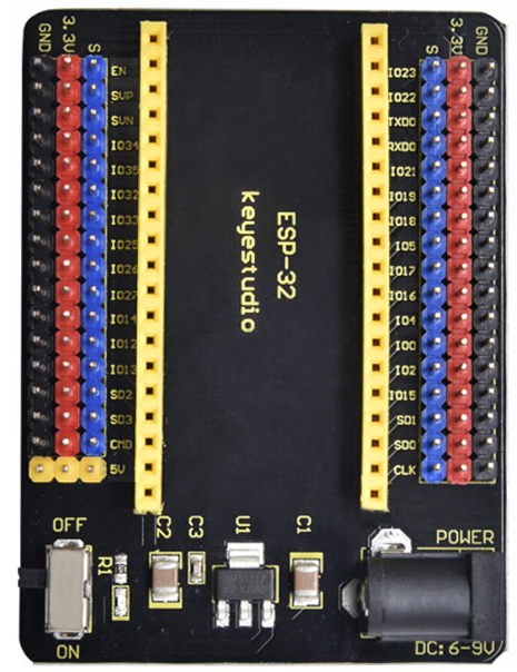
KEYES ESP-32 Sensor Shield
This provides 3-pin aconnections for all the ESP-32 Vroom pinout. So all the usual 3-pin cables and accessory boards can just plug in. Available HERE
Introduction
The keyestudio ESP32-IO shield is designed to be compatible with the keyestudio ESP32 Core board. The ESP32-IO shield has brought out all the pins of keyestudio ESP32 Core board to 3-pin connectors. In order to connect other sensors and actuators easily, the ESP32-IO shield connectors also have ground and DC 3.3V voltage.
In order to supply power to the keyestudio ESP32 Core board, the ESP32-IO shield has a power supply circuit. You only need to input DC 7-12V voltage on the black DC jack to power the keyestudio ESP32 Core board. And the ESP32-IO shield also comes with a small On-Off switch, for controlling the power.
Performance Parameters
- Supply voltage: DC 7-12V (NOT 6-9V as marked)
- Working current: 60mA
- Maximum power: 0.3W
- Operating temperature: -25℃ to +65℃
- Dimensions: 30mm*20mm
- Environmental attributes: ROHS
CONNECTING TO THE ESP32
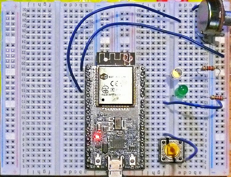
The ESP32 development boards have pins (19 pins each side, 0.1 inch spacing, 1.0 inch spacing between rows). This does not work for typical breadboards, but two breadboards can be used as in the photo on the left. The example here was used for testing many of the example sketches below.
We also have a "Sensor Shield" which ESP32 plugs into and which provides easy-to-use 3-pin connections for sensors and actuators, and onboard 3.3V power supply. See Previous section just above this.
Installing "ESP32 Arduino" into the Arduino ISP
You need to start with the latest Arduino IDE software. Go to the download page HERE and scroll to Download the Arduino IDE. In the green box on the right, find your system. For Windows, use Windows Installer unless you have an earlier version and know how to just add the ZIP file. Run the installed Arduino IDE system to make sure it works..
Next you will install ESP32 capability into the Arduino environment. This installs board definitions, code libraries and much more, to allow you to program the ESP32 in the familiar Arduino ISP software. This is what we use to write and test the example sketches below. Here are the steps:
[1] At the top menu bar go to File and then Preferences. In the lower part of the screen you will see something like this:
![]()
(I already had an entry for ESP8266, which you see here) But notice the square icon at far right. Click It
Now you will get a pop-up that looks like this:
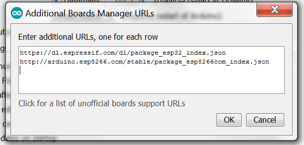
Add a line in the box (you can cut/paste) : https://dl.espressif.com/dl/package_esp32_index.json then click OK and back at Preferences again click OK
You have told the Arduino IDE where to find the ESP32 information. Now you need to actually get it downloaded and installed. This will take quite a while, once you start.
[2] Have the Boards Manager get the ESP32 information and install it. At the top menu bar go to Tools then Board then Boards Manager You’ll see a screen like this:

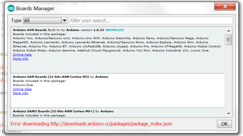
In the field "Filter Your Search" enter ESP32
Now you should see the esp32 by Espressif Systems entry like this:
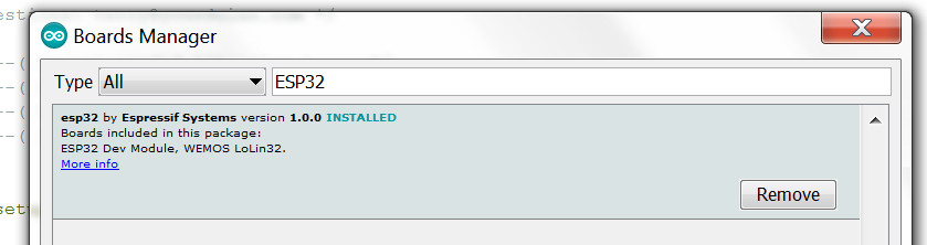
Move you mouse down into it, and at the lower right click on Install. (Mine shows it already installed in the photo)..
NOW watch the status bar at the lower edge of the box. Get coffee or Other: It will take quite a while.
DOWNLOAD AND INSTALL THE ESP32 USB DRIVERS
You probably do not have the USB drivers installed to support the CP2012 USB interface chip on your ESP32. Here’s what to do:
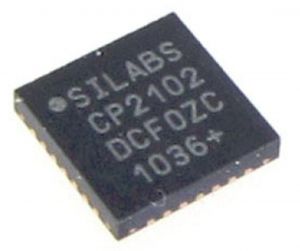
Look-Closely-Now at the small square USB interface chip next to the USB connector on your ESP32. (I need reading glasses!). It is probably a CP2102 like this:
Get and Install the Drivers: HERE: You need to pick the version for your version of Windows. For WIN7 pick the first (default) entry.
Put the downloaded ZIP file in a new folder. UNZIP it there. Now there are two possibilities:
[1] You plug your ESP32 into a USB connection and Windows prompts you to install a driver
1. Use the dialog to browse for the driver location
2. Locate the driver folder (that you previously unzipped)
3. Follow the instructions
[2] Manual Install
1. Using Windows File Explorer, locate the driver folder (that you previously unzipped)
2. Determine if you have 32-bit or 64-bit Windows
3. Double click to run the .exe file named CP210xVCPInstaller_xnn.exe (where xnn is x64 for 64-bit and x86 is for 32-bit)
4. Follow the instructions
That was not a lot of fun. But NOW the fun begins!
ESP32 Details
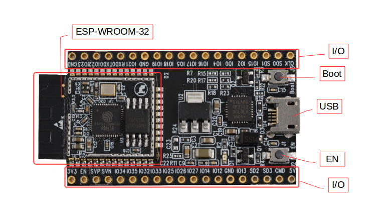
Micro-USB jack: The micro USB jack is used to connect the ESP32 to our computer through a USB cable. It is used to program the ESP module as well as can be used for serial debugging as it supports serial communication
EN Button: The EN button is the reset button of the ESP module. Pressing this button will reset the code running on the ESP module
Boot Button: This button is used to upload the Program from Arduino to the ESP module. It has to be pressed after clicking on the upload icon on the Arduino IDE. When the Boot button is pressed along with the EN button, ESP enters into firmware uploading mode. Do not play with this mode unless you know what you are doing.
Red LED: The Red LED on the board is used to indicate the power supply. It glows red when the board is powered.
Blue LED: The Blue LED on the board is connected to the GPIO2 pin. It can be turned on or off through programming. In some Chinese cloned boards like mine, this led might also be in red color.
I/O pins: This is where major development has taken place. Unlike ESP8266, on ESP32 we can access all the I/O pins of the module through the break-out pins. These pins are capable of Digital Read/Write, Analog Read/Write, PWM, IIC, SPI, DAC and much more.
CONNECTING YOUR ESP32 Module and TESTING IT
You need a "Micro-USB" cable to run your ESP32. Make SURE it is a real USB data cable, not a charger-only cable. (I got burned-and-confused with that!)
If you do not use a breadboard at this point, make sure the ESP32 will be on a non-conductive surface, like a magazine. Like MAKE, or The New Yorker, or Vermont Life, or any of those dumb catalogs that clog up your mailbox. Anyway, Plug the USB cable into your ESP32 and then into your computer’s USB port.
A Red LED should light up on your ESP32. That shows it is getting 5 Volt power over USB (An onboard regulator will provide 3.3V for the ESP32 chips).
Now: Start the Arduino IDE and let’s get things set up:
[1] Select your particular ESP32 board in the Arduino IDE. Click Tools then Board and you should see something like this:
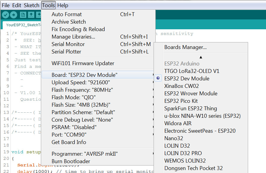
Select your board in the pulldown on the right. (You may have to scroll that section down).
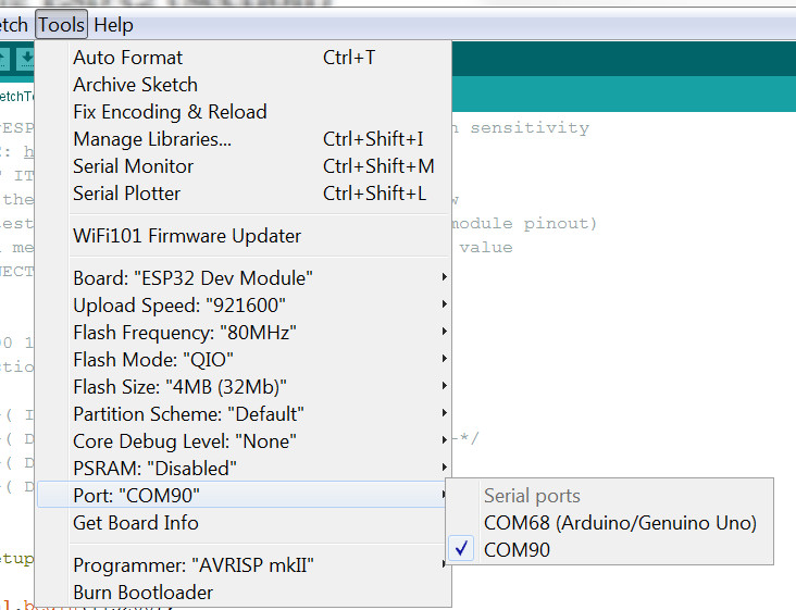
[2] Select your PORT. Click Tools then Port: . You should see a new COM port, labelled COM4 or something. Select it. (Mine shows an Arduino also connected).
[3] Open a New sketch: (Highlight and remove any template lines so you have a blank sketch page).
[4] In the section below "ESP32 EXAMPLE SKETCHES" click on YourESP32 Sketch WIFI Scan . Copy and paste it into your blank IDE page.
[5] At the top, click the button labelled Verify At the bottom green area you should see: ![]()
After several seconds (or longer for the first compile) you should see: 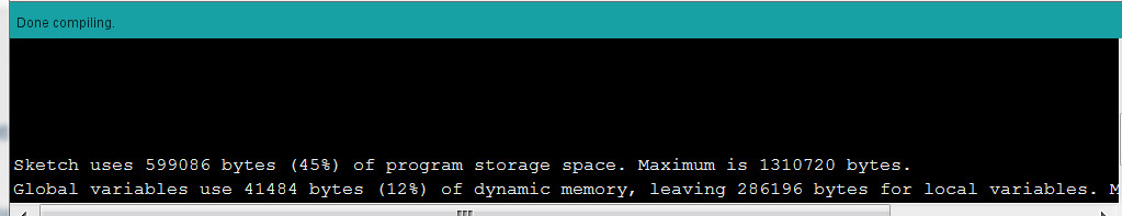
IF that’s OK, now Upload your sketch! Click the Upload button: 
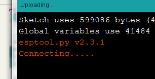
After several seconds you should see a "Connecting" message:
If all goes well, in a few seconds you show see this message:
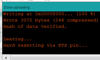
See the sketch work:
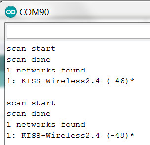
The Scan Wifi sketch tells your ESP32 to activate it’s WiFi radio and scan for any WiFi networks it can find. You will see the results on the Serial Monitor. At the upper right of the Arduino IDE screen you will see this: 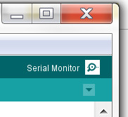 CLICK IT
A separate window will open. Look at the lower right and you will see a place to set the Baud Rate (Speed). Set it to 115200 as shown. 
NOW you should see data scrolling by on the Serial Monitor screen. In my log cabin in Vermont all it found was my local WiFi Router:
And. That’s All For Tonight!!
ESP32 TROUBLESHOOTING
Also see his excellent Books and classes on ESP-32.
ESP32 EXAMPLE SKETCHES
NOTE: Find all sketches with SEARCH on upper right. Search on "YourESP32 Sketch"
YourESP32 Sketch NodeMCU32S SimpleBLINK This is specific to the nodeMCU-32S module with built-in LED
ESP32 Memory Size Questions
(From compiling bare sketch with only setup and loop)
Sketch uses 173740 bytes (13%) of program storage space. Maximum is 1310720 bytes.
Global variables use 13272 bytes (4%) of dynamic memory, leaving 314408 bytes for local variables. Maximum is 327680 bytes.
ESP32 Reference Publications
ESP32 Projects
Rui Santos has an excellent ESP32 Education / Project series here:
ESP AND DEVICE TECHNICAL REFERENCE MATERIALS
The ESP TECHNICAL REFERENCE MANUAL
The EXPRESSIF Online Forums are HERE
ESP RECOMMENDED PIN USEAGE
The following table shows what pins are best to use as inputs, outputs and which ones you need to be cautious.
The pins highlighted in green are OK to use. The ones highlighted in yellow are OK to use, but you need to pay attention because they may have unexpected behavior mainly at boot. The pins highlighted in red are not recommended to use as inputs or outputs.
Источник: