


CAN Bus
Содержание

This evening has been full of research. I was looking at how to get different devices to communicate together with an Arduino or two monitoring temperature, voltage, speed, and so on. I then started looking to see if Arduino could somehow emulate a cars OBD2 drive so I could pretend I had a modern car that reported on what was going on under the hood
One thing led to another and it was a pretty nice eureka moment coming to the understanding of what CAN Bus and OBD2 (OBDII) actually were and that I could just use CAN itself to communicate to each Arduino device on its network, and expose that on the standard adapter that everyone plugs into.
Set into car
 Android head unit radio
I recall seeing things in the head unit regarding CAN bus. I started looking into how to resolve the “Set into car” button where it would tell me “No original vehicle setting function”. I went into Factory Settings and then looked at the first item protocol settings. From within, I saw the title of the app was actually “CAN set”. I was onto something!
Quite a few of the brands were unfamiliar. Raise, Hiworld, BNR, XBS, XINPU, Daojun, Oudi, Ruishengwei, HCY, Hechi, Ansheng, Bagu, Luzheng, Anyuan, NFCK, LH, CML … okay, all brands were unfamiliar. I’m assuming some of these are the Pronunciations of Chinese words. Perhaps Oudi is actually Audi, or maybe these are different protocols that sit on top of CAN bus.
I started poking around and saw “Raise” had an entry for “Electric car”. I selected that and went with the only option JRYG-M2 which had a can ID of 1034001.
I was able to go back to the car settings and click “Set into car”. Sure enough, it went ahead and showed me a new screen for an electric car.
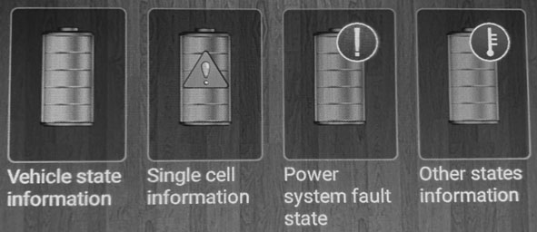
I had quite a few icons that led me to see temperatures, voltages, torque, current, etc. It was all blank but it was something. It was waiting for communications to be sent over the CAN bus.

 CAN bus RAISE Electric car JRYG-M2 car settings
Wires
 Rudimentary steering wheel controls on breadboard
Now we are at the last part where are the wires to hook up the CAN bus? I think this is where the steering wheel controls for KEY1 and KEY2 come into play. I think without CAN, these two wires are treated the same, simply for generic SWC with a 0-5k resistance to ground. I suspect that KEY 1 and KEY 2 are CAN High and CAN Low wires.
Implementation
I’m under the impression that I just need to look at the OBD2 format of a few setting sand test sending it over the CAN bus to verify it the device starts picking it up. Once that part is done actually acquiring the data is a fairly heavy task as well.
Playing with CAN is another project on its own. I think eventually I’ll look into playing with CAN modules later. I’ve seen quite a few gadgets to hook up Arduino’s over the network using an TJA1050 CAN controller interface chip. One model I’ve seen is LDTR-WG0210, compatible with the ISO 11989 standard.
Update
I just received a reply from the seller with a manual for A2222 Android Products Operation Manual: Android Interface Instruction. It’s much better than what came with the device. I’ve worked out quite a bit of it on my own already, but it’s nice to see a confirmation that I went in the right direction. This is what they say about features related to canbus:
Support steering wheel control (don’t support cars need a canbus)
They also replied directly this is a universal double din car stereo, and that if my car needs a canbus, it will not support the steering wheel control.
I think I’m out of luck. I was hoping I could choose to either have those two KEY wires for either SWC or CAN bus like you could only choose between the two, but used SWC by default until the canbus settings were setup. It would have made more sense of why the same resistance on both of the KEY wires couldn’t be mapped to two separate steering wheel controls.
I could go ahead and try to experiment later with canbus just to make sure, but by that time, I may just go with another radio that does support it.
Источник: