


PWM Tutorial for Arduino, ESP8266 and ESP32
Содержание
In this tutorial you learn what Pulse Width Modulation (PWM) is and how to create different PWM signals from your Arduino, ESP8266 or ESP32 microcontroller.
In two detailed example you change the brightness of an LED and control the speed of a DC motor by using the PWM signal from the microcontroller.
Table of Contents
How does PWM for Microcontroller Work?
The digital inputs / outputs on your microcontroller have a constant voltage of 3.3V (for ESP8266 and ESP32 boards) or 5V (for Arduino boards). But in some cases you want to control the voltage to a specific value between 0V and the maximum voltage.
In case of PWM, a signal is pulsing between HIGH (3.3V or 5V) and LOW (0V). How often the signal is changing between HIGH and LOW is defined by the PWM frequency. The PWM frequency on Arduino pins are 976 cycles per seconds (Herz), for the ESP8266 up to 1 kHz and for the ESP32 up to 40 MHz.
To generate a PWM signal you use the function analogWrite(pin, value). This function create a square wave PWM signal. You can control the shape of the PWM signal with the duty cycle of (value/255). A 0% to 100% duty cycle corresponds to a value between 0 and 255.
The following table shows broadly the relation between the duty cycle and the average output voltage if the maximum voltage is 5V for Arduino microcontroller and 3.3V for ESP8266 and ESP32 microcontroller.
| Duty Cycle | Output voltage (Arduino) | Output voltage (ESP8266 and ESP32) | analogWrite(X) |
|---|---|---|---|
| 0% | 0V | 0V | 0 = 0%*255 |
| 0.25% | 1.25V | 0.825V | 63.75 = 25%*191.25 |
| 0.5% | 2.5V | 1.65V | 127.5 = 50%*255 |
| 0.75% | 3.75V | 2.475V | 191.25 = 75%*255 |
| 100% | 5V | 3.3V | 255 = 100%*255 |
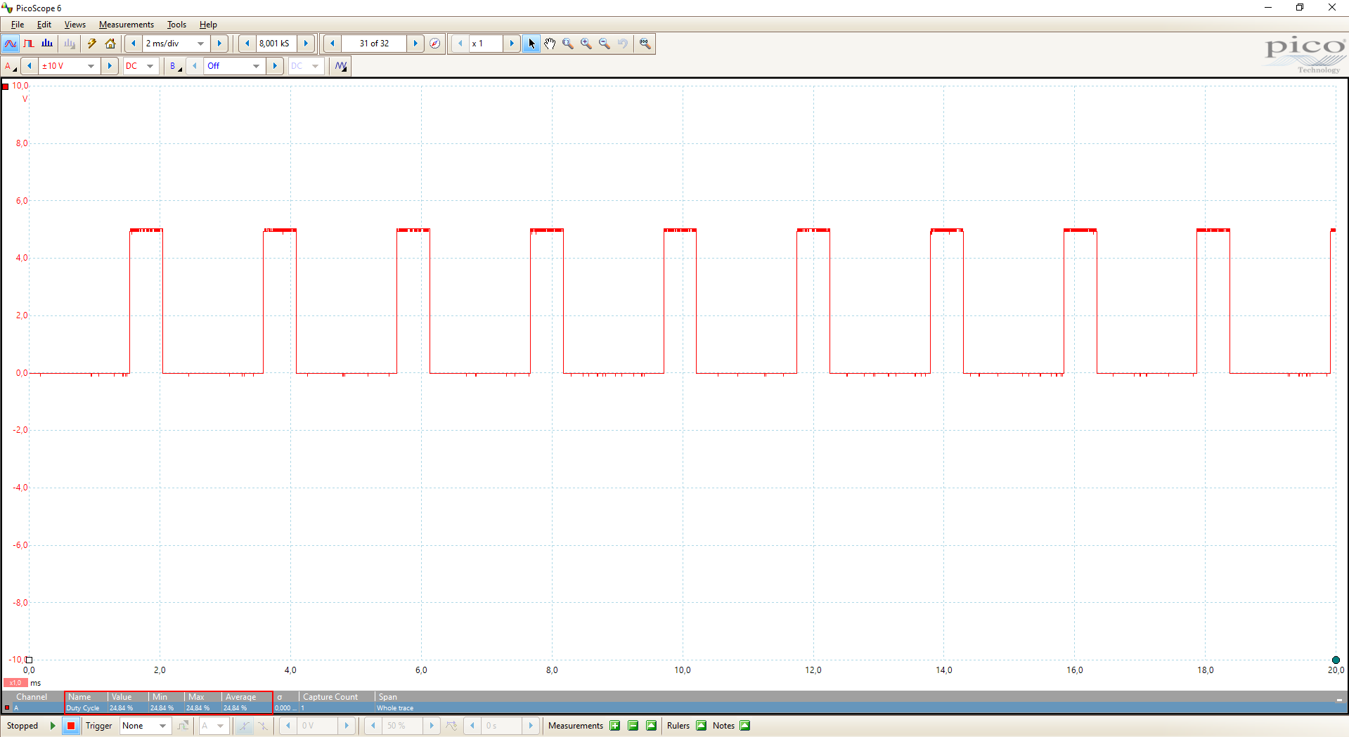
I used my oscilloscope to measure the duty cycles of the table above for the Arduino output voltage. Therefore I connected digital pin 11 of the Arduino Uno to my PicoScope and set up a measurement for the duty cycle. You can do the exactly same measurement for the ESP8266 or the ESP32
The code for the quick measurement is the following. For each measurement I changed the value for the analogWrite function.
Duty Cycle 0%
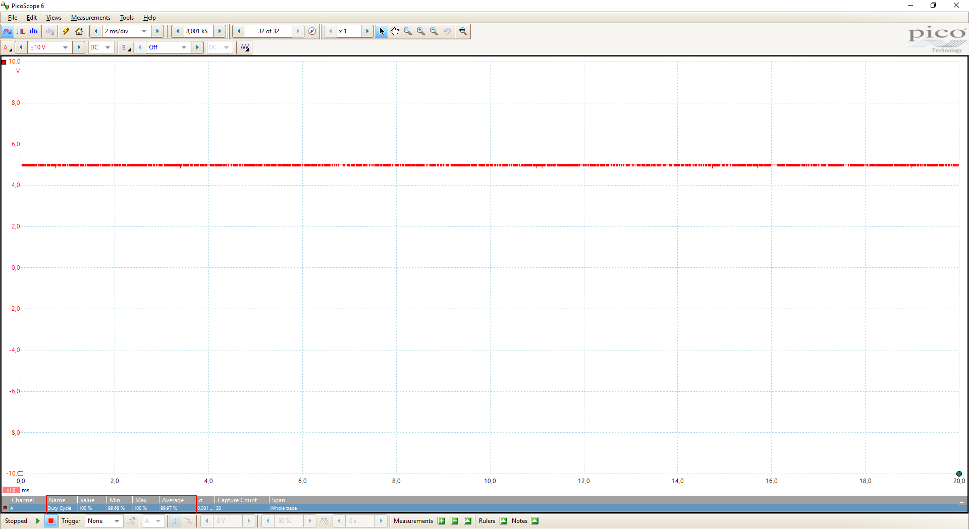
Note that the 0% duty cycle is measured as 100% because there is no square wave at 0% and also at 100%. Therefore be careful how the duty cycle is measured. In my case I have to see if the voltage is 0 at 100% duty cycle.

Duty Cycle 25%
Duty Cycle 50%

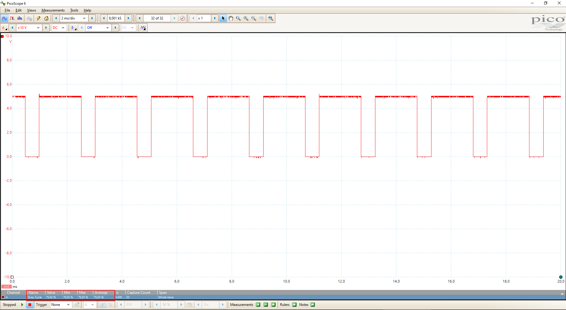
Duty Cycle 75%
Duty Cycle 100%
The following table gives you an overview of all components and parts that I used for this tutorial. I get commissions for purchases made through links in this table.
| Component | Amazon Link | AliExpress Link |
|---|---|---|
| Arduino Nano | Amazon | AliExpress |
| Arduino Pro Mini | Amazon | AliExpress |
| Arduino Uno | Amazon | AliExpress |
| Arduino Mega | Amazon | AliExpress |
| ESP32 ESP-WROOM-32 | Amazon | AliExpress |
| ESP8266 NodeMCU | Amazon | AliExpress |
| ESP8266 WeMos D1 Mini | Amazon | AliExpress |
| Resistor and LED in Package | Amazon | AliExpress |
| DC Motor | — | AliExpress |
| L298N Motor Driver Module | — | AliExpress |
| DC Motor with L298N Motor Driver Module | Amazon | — |
How to Change the Brightness of an LED by PWM
In the following example we want to change the brightness of an LED by changing the duty cycle of the regarding PWM signal.

The following fritzing sketches show the circuit done with different Arduino, ESP8266 and ESP32 microcontroller boards. We have to make sure that the LED is connected to a microcontroller pin that is PWM able.
I recommend to get the Microcontroller Datasheet eBook where you can find the pinouts of the different microcontroller boards, that include the information which pins are able to use PWM. You get the eBook for free if you join the DIYI0T newsletter.
Wiring between LED and Arduino Microcontroller for PWM
The following pictures show the wiring between different Arduino boards, the LED that brightness we want to control and a 220Ω resistor to prevent the LED from too high voltages.
For this example I use the digital pin 11 that is able to create PWM signals but you can use any other PWM able pin as well.
For more information about the Arduino Nano, visit the Arduino Nano Tutorial.
For more information about the Arduino Uno, visit the Arduino Uno Tutorial.
For more information about the Arduino Mega, visit the Arduino Mega Tutorial.
Wiring between LED and ESP8266 Microcontroller for PWM
The following pictures show the connection between different ESP8266 boards like the ESP8266 NodeMCU or the ESP8266 WeMos D1 Mini and the LED as well as the 220Ω resistor.
We need a resistor in series to the LED to prevent the LED for too high voltages.
You can choose any digital I/O pin of the ESP8266 for this example, because all digital I/O pins of the ESP8266 are able to create PWM signals, but make sure that you also change the pin in the program script. I select pin D4 for this example.
Wiring between LED and ESP32 Microcontroller for PWM
The following picture shows the wiring between the ESP32 ESP-WROOM-32 microcontroller board, the LED and the 220Ω resistance to prevent the LED for too high voltages.
Because any digital I/O pin of the ESP32 is able to create PWM signals, you can choose any other digital pin but make sure to change the program script. In my case, I connect pin 4 of the ESP32 to the LED.
Program Code to Change the Brightness of an LED by PWM
The program code is pretty straight forward. We have to define the pins and some variables for the time and the height to increment the brightness of the LED. If you want to know how to change the color for multicolor LEDs, using different PWM signals, you find this in my LED tutorial.
In the first part of the Arduino code, we define the pin that connects the LED to the microcontroller. Because this script is for Arduino, ESP32 and ESP8266 microcontrollers, you have to comment out two of the first three lines that defines the pin.
Also we have to define three additional variables:
- bright: initial value of the LED brightness and therefore 0 to shut down the LED.
- increment: the incremental change in the PWM frequency. Each increment the LED increases and decreases the brightness.
- time: the time period in milliseconds for each PWM cycle.
In the setup function, we fine the pin, that we defines as LED pin at the beginning of the script, as output pin to use the pin with PWM.
We start the loop function, with the analogWrite(pin, value) function we set the analog value (PWM wave) for the brightness to the LED pin. After the delay of 0.1 seconds, the brightness in incremented. If the brightness reaches the minimum (0) or maximum (255) value, the increment is changed from a positive value to a negative value.
The following video shows the change of the brightness of the LED due to the PWM function.

By loading the video, you agree to YouTube's privacy policy.
Learn more
Источник: