


The Arduino Simulator you’ve been looking for!
Содержание
- Overview
- What is an Arduino simulator?
- Why are simulators so cool?
- How do you use a simulator?
- Other aspects of TinkerCAD
- In Summary
Are you on the lookout for a good Arduino simulator? Wondering what an Arduino simulator is? We’ve gotten a lot of questions about Arduino simulators, and if a good simulator exists, so keep watching to find out more!
Overview
In this video we’ll cover:
- WHAT an Arduino simulator is
- WHY you should be checking them out
- HOW to use popular Arduino simulator called Tinkercad (which is free)
What is an Arduino simulator?
An Arduino simulator is a virtual representation of a real world Arduino circuit.
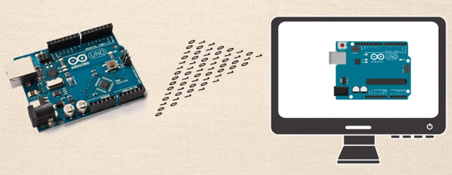
What does that actually mean? Let’s look at an example. Now some people have different interpretations of what the famous “Hello World” circuit is. Some say it’s your first project where you create a simple blinking LED circuit; others claim it’s when you have an LCD display that says “Hello world!”
For our purposes, we are just trying to create the the most simple of circuits, so we are referring to the interpretation where you just have a blinking LED circuit.
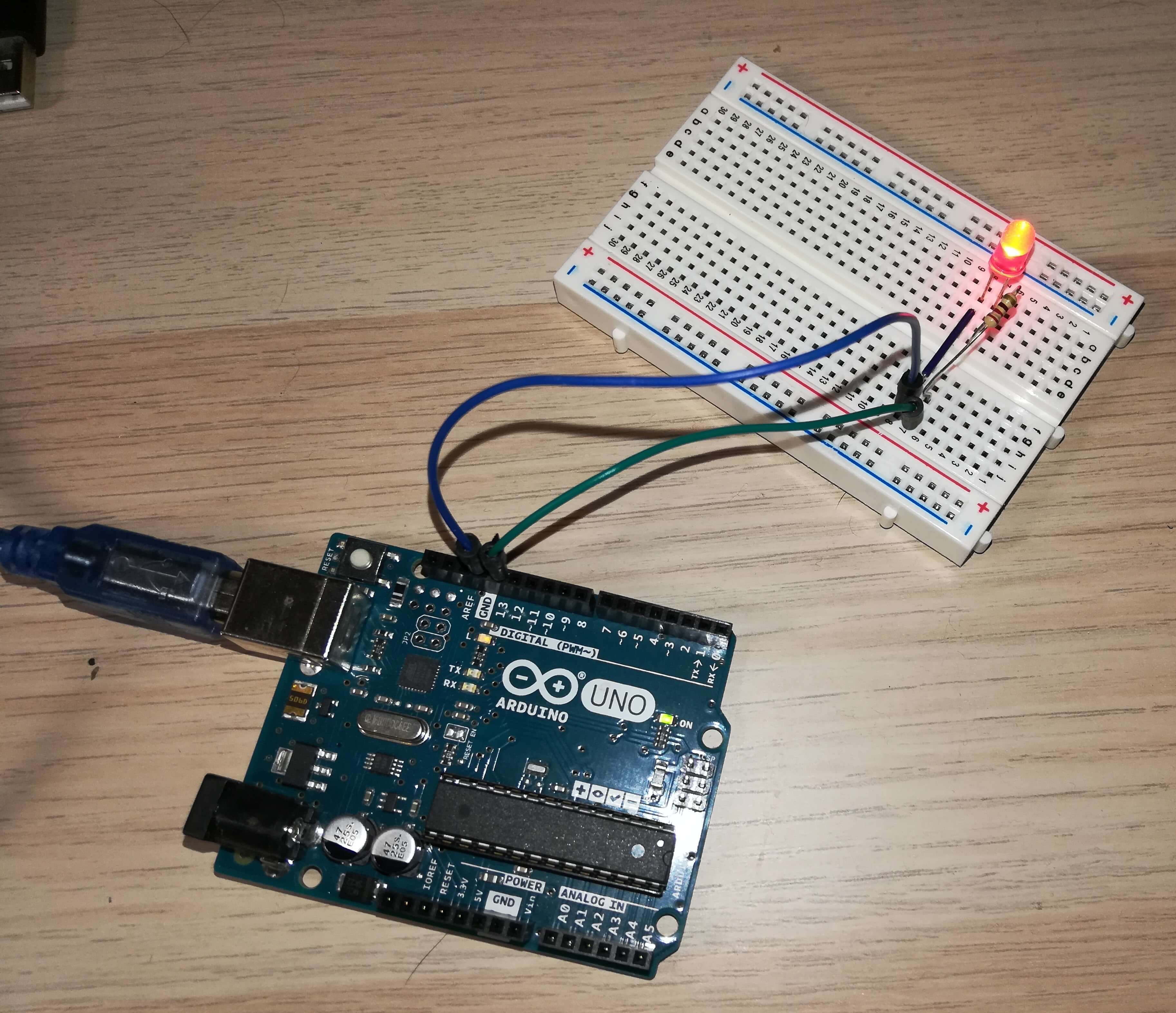
So we’ve setup the circuit, we’ve programmed the code in the Arduino IDE, we’ve uploaded it, and now we have a real world, physical circuit that blinks the LED. This took about 6 minutes to construct.
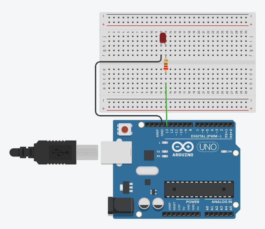
Next we’ll use the free online Arduino simulator software at TinkerCAD. In about 2 minutes we’ve created exactly the same circuit, we’ve used the same exact code, and after hitting the “start simulation button”, we have a virtual version of exactly the same circuit. That is some serious efficiency!
We’ll show you at the end of the video exactly how to make that demo.
Why are simulators so cool?
You’ve already seen how it can be much quicker to build stuff online so we won’t belabor that point. Here are some other reasons why simulators rock:
- You can learn how to code and build circuits from anywhere you have a computer and internet access.
- It’s much easier to track down hardware / wiring errors in the simulator. It can be very difficult to visualize which wires are connected to which pins on a busy breadboard, but if you get it right in the simulator, then recreating it in the real world goes much smoother.
- You can share your design with peers for feedback and to help troubleshoot issues, and the person reviewing your design is able to see both the hardware and coding side of your project at the same time.
How do you use a simulator?
Next we’ll show you exactly how to build the blinking LED circuit from previously. First go to TinkerCAD and setup an account if you don’t already have one. After that you’ll find yourself in the dashboard, this is where we can view previous designs or choose to create a new one.

Once your at the dashboard, click on the “Create new Circuit” button. Now you’ll see the “workspace”, this is really where the magic happens. On the right hand side you can see where you can click and drop the various components.
One thing to note: you can select Components Starters Arduino and here you can access a bunch of premade circuits which are called assemblies. You can click and drop the “Blink” assembly, which will provide all the necessary components, as well as the code to make the circuit run.
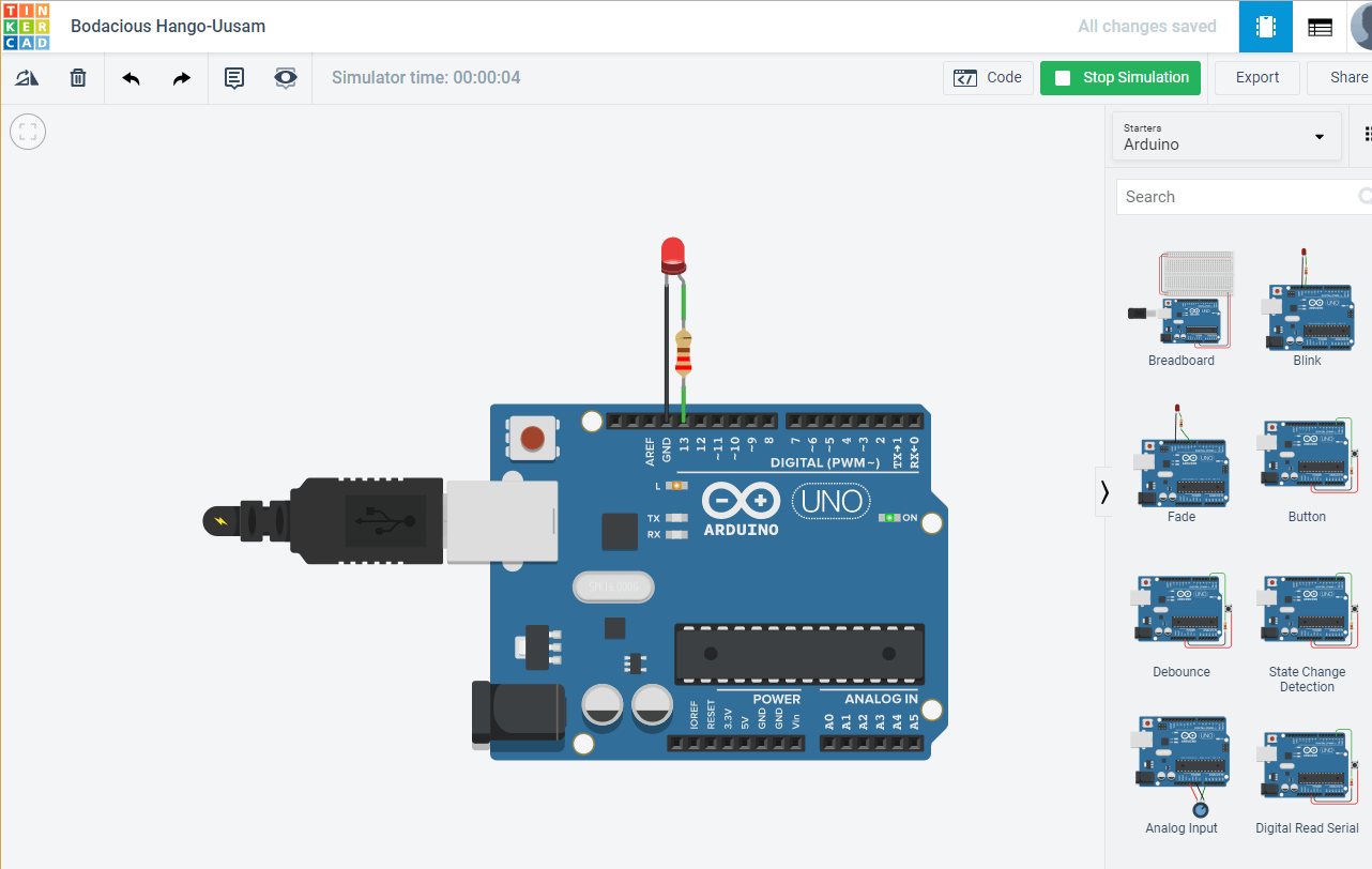
If you click “Start Simulation” you will see this circuit functions as advertised. So let’s create it from scratch instead. The first thing we will want to do is make sure we have components placed in our project. Type in “Arduino” in the components side menu and then click and drop the UNO3.

PRO-TIP 1: To pan the view around, just click and hold anywhere in the workspace to move it around.
Next, let’s drop a breadboard. After that, we’ll drop an LED. Find it in the components list, then carefully drop it onto the breadboard. You can see where the cathode or anode connects to specific pins on the board.
Another cool thing is you can click on the various components to change their characteristics. You can change the colors of LEDs, the resistance value of resistors, and the color of the wires, to name a few.
Lastly we will wire it up. You do not find wires in the component list, you simply click on either the breadboard or the Arduino pins with the left mouse button and a wire begins.
PRO-TIP 2: When creating the wires, every time you click you add a “node” in the wire which allows you to keep things very organized. Also changing the colors of the wires can keep things very organized as well.
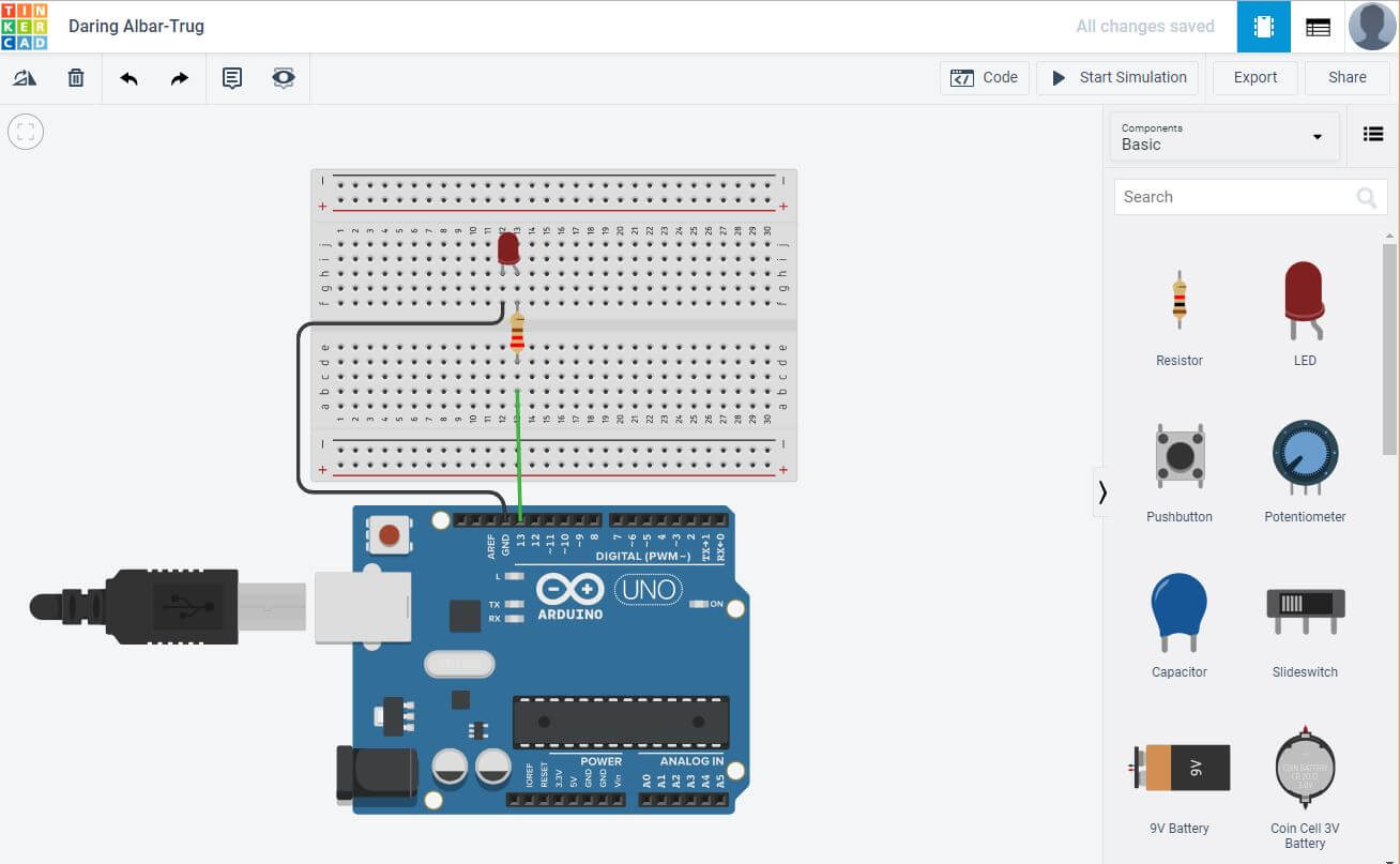
So that’s how you build the circuit. Let’s look at the code. You can see it’s already preloaded with a sketch because we had previously selected the “Blink” starter assembly. You can also see it’s in a format that may seem a little unusual, “block view“. You can mess around with this view if you want, but we typically like to view the code in “text view” which is the same as the official Arduino IDE.
The purpose of this lesson is not to teach the code but rather show you the simulator, so let’s click the “Start Simulation” button and there you have it, a functioning blinking LED circuit.
PRO-TIP 3: Sometimes you’ll start the simulation, and then get distracted by something, and then try to edit either the code or the hardware. If the simulator is still running, you will not be able to edit anything, and sometimes the only indicator that the sketch is still running is the green box that says “Stop Simulation”. If you can’t seem to edit anything, make sure your simulation is not running.
Other aspects of TinkerCAD
So that’s how you build a very basic blinking LED circuit in TinkerCAD. There are lots of other really cool things about Tinkercad which we’ll explore now.
Go to your main dashboard by clicking the TinkerCAD logo at the top left of the screen, then click the “Learn” tab at the top right of the screen. Next click the drop down button (which defaults to 3D) and select “Circuits”. Here you can select various start guides and lessons.
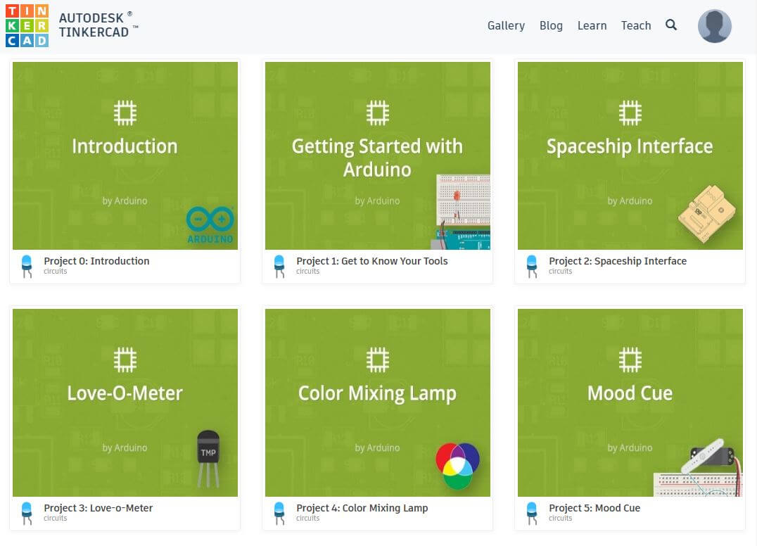
If you select “Projects”, then “Show all Arduino”, you can see various projects at the bottom with the green backgrounds. All of these projects correspond to the starter projects that are included in the the official Arduino.CC starter kit, which is super helpful if you have that kit and want to follow along.
If you’re just trying to get some inspiration, learn new skills, or check out new stuff, go over to the “Gallery” tab. Again, make sure to select “Circuits”, and from here you can see a variety of projects from the community.
You can also search for specific projects which is useful if you’re struggling with a particular project and you’re wondering if someone else has already created it.
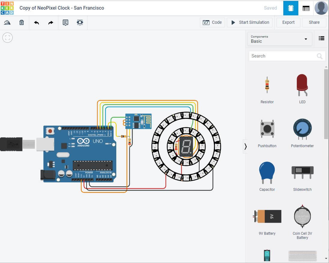
Once you find a project you like you can click on it, then click “Copy and Tinker”, and you are now able to explore and edit the users project. You can leave a comment, check out their code, and make any modifications that you desire.
In Summary
You can see how there’s tons of really useful stuff on Tinkercad. It’s not only a great place to design circuits, but also a great place to learn from the community and get inspiration.
How do you use the simulator? Do you like creating projects virtually first, do you like to dive right into the physical world? Let us know in the comments below, we’d really appreciate it. Have a great day!
Источник: