


Arduino Nano Tutorial – Pinout Schematics
Содержание
In this guide, learn about Arduino Nano pin outs and diagrams. We’ve created a well explained, diagram based pin out representation of Arduino Nano.
Arduino Nano Pinout
The Arduino Nano, as the name suggests is a compact, complete and bread-board friendly microcontroller board. The Nano board weighs around 7 grams with dimensions of 4.5 cms to 1.8 cms (L to B). This article discusses about the technical specs most importantly the pinout and functions of each and every pin in the Arduino Nano board.
How different is Arduino Nano?
Arduino Nano has similar functionalities as Arduino Duemilanove but with a different package. The Nano is inbuilt with the ATmega328P microcontroller, same as the Arduino UNO. The main difference between them is that the UNO board is presented in PDIP (Plastic Dual-In-line Package) form with 30 pins and Nano is available in TQFP (plastic quad flat pack) with 32 pins. The extra 2 pins of Arduino Nano serve for the ADC functionalities, while UNO has 6 ADC ports but Nano has 8 ADC ports. The Nano board doesn’t have a DC power jack as other Arduino boards, but instead has a mini-USB port. This port is used for both programming and serial monitoring. The fascinating feature in Nano is that it will choose the strongest power source with its potential difference, and the power source selecting jumper is invalid.
Like to do an exciting course on Arduino with 12+ Projects?
We have developed a comprehensive course on Arduino named “Arduino Course [Zero to Hero] – Learn By Doing Projects”. The course is published in partnership with Udemy – the worlds best online education platform. If you are looking to master Arduino and develop a couple really exciting projects using the Arduino platform, enrolling in this course would be the best decision you can make to achieve your dreams. So lets take a quick look at what all you will learn in this course.
Our course “Arduino Course [Zero to Hero]” follows a complete learn by doing approach, where you will be learning each and every concept by doing a project. The course is designed with 12+ projects ranging from easy, medium, and advanced projects. The course begins by introducing basic concepts and simple led based projects, and then moves on to explain mid level concepts like sensor interfacing, sensor based projects and finally the course teaches you how to do advanced projects and IoT (Internet of Things) based projects using the Arduino platform.

You will do the following projects in this full video course:
- Automatic Hand Sanitizer/Soap Dispenser
- Automatic Light Control using LDR
- Generating Patterns with LED’s
- Smart Door Lock using Keypads (Digital Code Lock)
- Home Security System (Protect against Fire accident, Gas leakage,)
- Weather Monitoring System (Measure Temperature Humidity)
- Home Automation using Smartphone TV Remote Control
- Line Follower Robot (the basics to build robots)
- Obstacle Avoidance Robot (learn to build intelligence in robots)
- Mobile Phone controlled Robot Car (wireless controlled robots)
- Smart Irrigation System
- IoT based Weather Station (Display weather data on website/web application)
Arduino Nano – Specification
| Arduino Nano | Specifications |
|---|---|
| Microcontroller | ATmega328P |
| Architecture | AVR |
| Operating Voltage | 5 Volts |
| Flash Memory | 32 KB of which 2 KB used by Bootloader |
| SRAM | 2KB |
| Clock Speed | 16 MHz |
| Analog I/O Pins | 8 |
| EEPROM | 1 KB |
| DC Current per I/O Pins | 40 milliAmps |
| Input Voltage | (7-12) Volts |
| Digital I/O Pins | 22 |
| PWM Output | 6 |
| Power Consumption | 19 milliAmps |
| PCB Size | 18 x 45 mm |
| Weight | 7 gms |
Arduino Nano Pinout Description
Taking this pin-out diagram below as reference, we shall discuss all the functionalities of each and every pin.
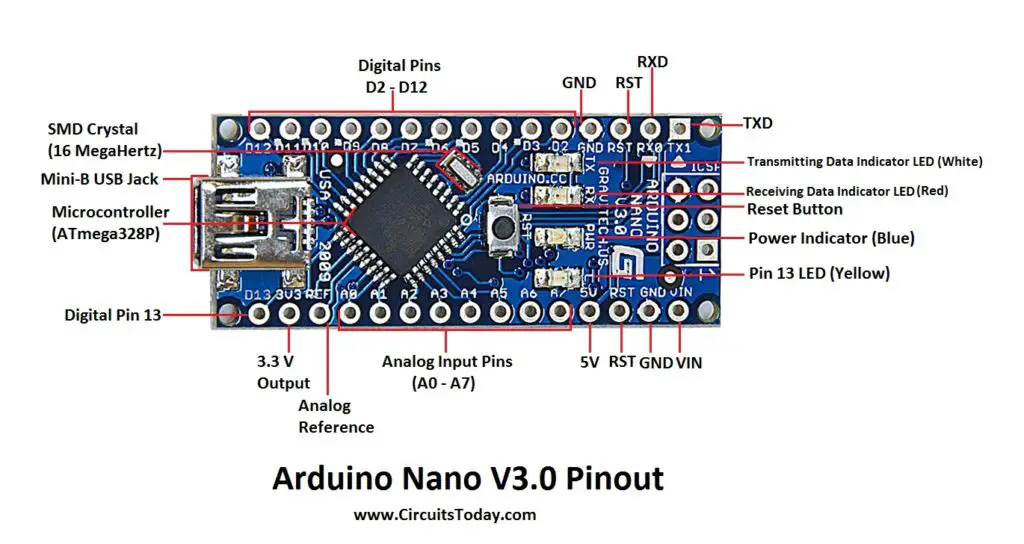
Arduino Nano Pinout
We can infer from the image that Arduino Nano got 36 pins in total. We will see all the pins section wise as well as a detailed format at last.
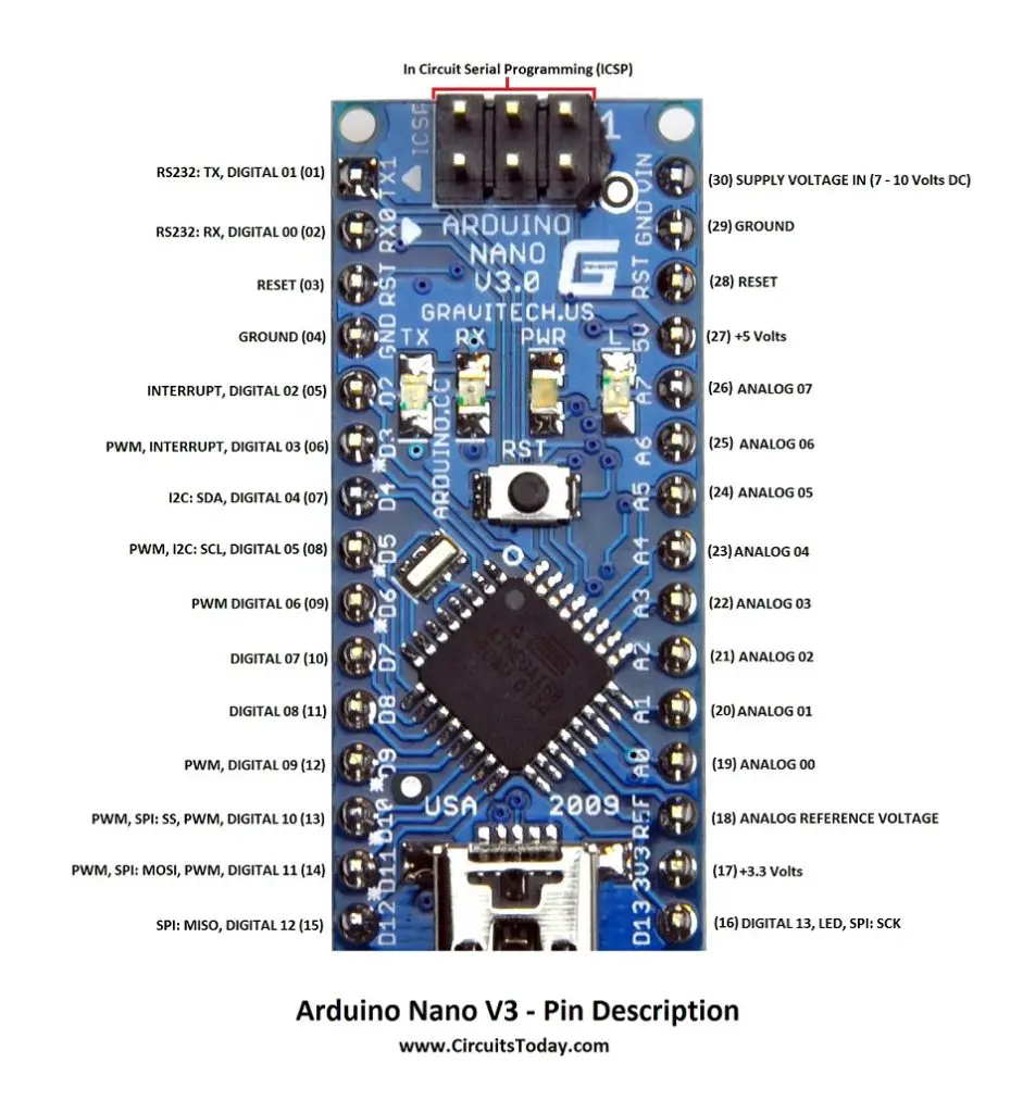
Arduino Nano Pin Description
Arduino Nan0 – Pin Description
Pins 1 to 30

| Arduino Nano Pin | Pin Name | Type | Function |
|---|---|---|---|
| 1 | D1/TX | I/O | Digital I/O Pin Serial TX Pin |
| 2 | D0/RX | I/O | Digital I/O Pin Serial RX Pin |
| 3 | RESET | Input | Reset ( Active Low) |
| 4 | GND | Power | Supply Ground |
| 5 | D2 | I/O | Digital I/O Pin |
| 6 | D3 | I/O | Digital I/O Pin |
| 7 | D4 | I/O | Digital I/O Pin |
| 8 | D5 | I/O | Digital I/O Pin |
| 9 | D6 | I/O | Digital I/O Pin |
| 10 | D7 | I/O | Digital I/O Pin |
| 11 | D8 | I/O | Digital I/O Pin |
| 12 | D9 | I/O | Digital I/O Pin |
| 13 | D10 | I/O | Digital I/O Pin |
| 14 | D11 | I/O | Digital I/O Pin |
| 15 | D12 | I/O | Digital I/O Pin |
| 16 | D13 | I/O | Digital I/O Pin |
| 17 | 3V3 | Output | +3.3V Output (from FTDI) |
| 18 | AREF | Input | ADC reference |
| 19 | A0 | Input | Analog Input Channel 0 |
| 20 | A1 | Input | Analog Input Channel 1 |
| 21 | A2 | Input | Analog Input Channel 2 |
| 22 | A3 | Input | Analog Input Channel 3 |
| 23 | A4 | Input | Analog Input Channel 4 |
| 24 | A5 | Input | Analog Input Channel 5 |
| 25 | A6 | Input | Analog Input Channel 6 |
| 26 | A7 | Input | Analog Input Channel 7 |
| 27 | +5V | Output or Input | +5V Output (From On-board Regulator) or +5V (Input from External Power Supply |
| 28 | RESET | Input | Reset ( Active Low) |
| 29 | GND | Power | Supply Ground |
| 30 | VIN | Power | Supply voltage |
ICSP Pins
| Arduino Nano ICSP Pin Name | Type | Function |
|---|---|---|
| MISO | Input or Output | Master In Slave Out |
| Vcc | Output | Supply Voltage |
| SCK | Output | Clock from Master to Slave |
| MOSI | Output or Input | Master Out Slave In |
| RST | Input | Reset (Active Low) |
| GND | Power | Supply Ground |
Arduino Nano Digital Pins
As mentioned earlier, Arduino Nano has 14 digital I/O pins that can be used either as digital input or output. The pins work with 5V voltage as maximum, i.e., digital high is 5V and digital low is 0V. Each pin can provide or receive a current of 40mA, and has a pull-up resistance of about 20-50k ohms. Each of the 14 digital pins on the Nano pinout can be used as an input or output, using pinMode(), digitalWrite(), and digitalRead() functions.
Other than the digital input and output functions, the digital pins have some additional functionality as well.
Serial Communication Pins
These two pins RX- receive and TX- transmit are used for TTL serial data communication. The pins RX and TX are connected to the corresponding pins of the USB-to-TTL Serial chip.
PWM Pins
Each of these digital pins provide a Pulse Width Modulation signal of 8-bit resolution. The PWM signal can be generated using analogWrite () function.
External Interrupts
When we need to provide an external interrupt to other processor or controller we can make use of these pins. These pins can be used to enable interrupts INT0 and INT1 respectively by using the attachInterrupt () function. These pins can be used to trigger three types of interrupts such as interrupt on a low value, a rising or falling edge interrupt and a change in value interrupt.
SPI Pins
When you don’t want the data to be transmitted asynchronously you can use these Serial Peripheral Interface pins. These pins support synchronous communication with SCK as the synchronizing clock. Even though the hardware has this feature, the Arduino software doesn’t have this by default. So you have to include a library called SPI Library for using this feature.
LED
If you remember your first Arduino code, blinking LED, then you’ll definitely came across this Pin16. The pin 16 is being connected to the blinking LED on the board.
Arduino Nano Analog Pins
As mentioned earlier UNO got 6 analog input pins but Arduino Nano has 8 analog inputs (19 to 26), marked A0 through A7. This means you can connect *8 channel analog sensor inputs for processing. Each of these analog pins has a inbuilt ADC of resolution of 1024 bits (so it will give 1024 values). By default, the pins are measured from ground to 5V. If you want the reference voltage to be 0V to 3.3V, we can give 3.3V to AREF pin (18 th Pin) by using the analogReference () function.
Similar to digital pins in Nano, analog pins also got some other functions as well.
I2C
Since SPI communication also has its disadvantages such as 4 essential pins and limited within a device. For long distance communication we use the I2C protocol. I2C supports multi master and multi slave with only two wires. One for clock (SCL) and another for data (SDA). For using this I2C feature we need to import a library called Wire library.
AREF
As mentioned already the AREF- Analog Reference pin is used as a reference voltage for analog input for the ADC conversion.
Reset
Reset pins in Arduino are active LOW pins which means if we make this pin value as LOW i.e., 0v, it will reset the controller. Usually used to be connected with switches to use as reset button.
ICSP
ICSP stands for In Circuit Serial Programming, which represents one of the several methods available for programming Arduino boards. Ordinarily, an Arduino bootloader program is used to program an Arduino board, but if the bootloader is missing or damaged, ICSP can be used instead. ICSP can be used to restore a missing or damaged bootloader.
Each ICSP pin usually is cross-connected to another Arduino pin with the same name or function. For example, MISO on Nano’s ICSP header is connected to MISO / digital pin 12 (Pin 15); MOSI on the ISCP header is connected to MOSI / digital pin 11 (Pin 16); and so forth. Note, MISO, MOSI, and SCK pins taken together make up most of an SPI interface.
We can use one Arduino to program another Arduino using this ICSP.
| Arduino as ISP | ATMega328 |
|---|---|
| Vcc/5V | Vcc |
| GND | GND |
| MOSI/D11 | D11 |
| MISO/D12 | D12 |
| SCK/D13 | D13 |
| D10 | Reset |
RESET
Power
Applications
We have compiled a huge list of Arduino Nano based projects with complete source code and detailed explanation of the circuits. Check out the list below.
Источник: