


How to set up IR Receiver and IR Remote on Arduino? Arduino IR Receiver Tutorial
In this project, we will learn how to set up an IR Receiver and an IR Remote on an Arduino and how the Arduino IR Receiver Interface works.
An IR Receiver or an Infrared Receiver is an electronic device that receives information from an IR Remote, decodes the signal, and sends it to another device like a Microcontroller. A common application for IR Receivers is our TV Remotes.
TV’s Remote Control sends infrared signals when any key or button is pressed. The IR Receiver, which is present at the front of the TV, will receive this signals and send them to a control circuit inside the TV after decoding them. The controller will then perform necessary action.
IR Communication is wireless, less expensive and very easy to implement. This makes it one of the widely used wireless communication technologies.
Hence, we will see how to use IR Receiver and IR Remote with Arduino, with the help of which, you can get an idea on how to implement IR Communication with Arduino and use it in a variety of projects like Robot Control, Security Systems, Distance Measurement, Heart Rate Monitors, Proximity Sensors, etc.
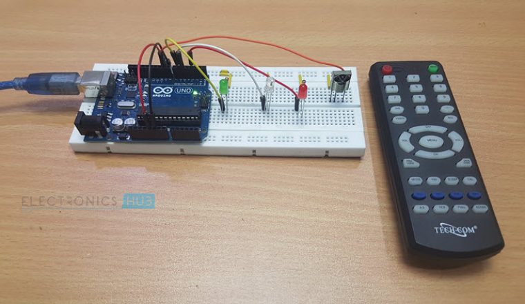
In this project, we will interface TSOP1738, which is an IR Receiver to Arduino UNO and control three LEDs through a simple IR Remote Control.
Basics of IR Communication
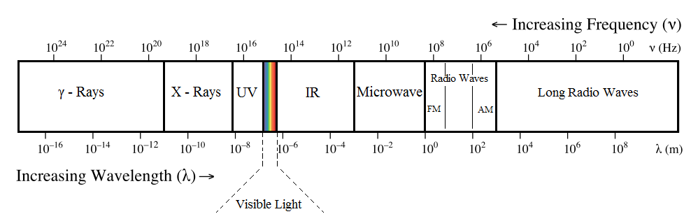
IR or Infrared Communication is based on, well, Infrared Light. Infrared Light or Infrared Radiation is also a type of light whose wavelength is higher than that of the Visible Light. Hence, we cannot see the Infrared Light.
This makes it a good choice for Wireless Communication. But the only limitation is that IR Communication requires line-of-sight between the transmitter and receiver. Hence, IR Communication cannot be used through walls or barriers like Bluetooth or WiFi.
How IR Communication Works?
In every IR Communication set up, there are two main components known as the IR Transmitter and the IR Receiver. As the name suggests, an IR Transmitter transmits IR Radiation. A simple IR Transmitter is an IR LED. It looks like a regular LED but emits Infrared Light.
An IR receiver on the other hand, consists of a Photo Diode and an Amplifier circuit to convert the detected IR Light in to electrical signals. An example of IR Receiver is the TSOP1738 IC.
Now coming to the working of IR Communication, Infrared Light is everywhere i.e. every object emits infrared radiations. The sources of infrared light can be anything from Sun, Light Bulb to Humans and animals.
This means that there is a chance of interference and noise while using IR Communication. Hence, we need to modulate the Infrared light and then transmit the IR Signals so that only the intended signal is transmitted.

At the transmitter of the IR Communication i.e. at the IR Remote for example, an encoder is used to modulate a binary signal and the modulated signal is applied to the IR LED. Infrared Light from the IR LED is now modulated according to the modulated signal and is transmitted through air.
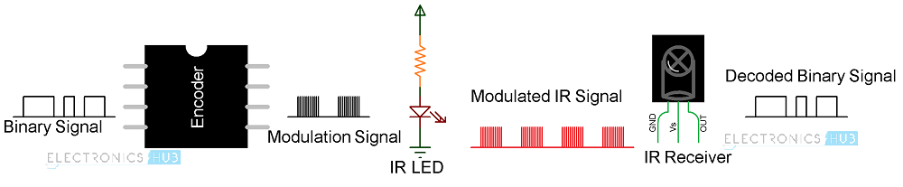
The modulated IR Signal is then received by the IR Receiver, which demodulates the IR Light and converts it back to the original binary signal. This binary signal is then transmitted to a Microcontroller.
During Modulation, the IR Light is made to turn ON and OFF at a particular frequency called Carrier Frequency. Only the IR Receiver which is tuned to this frequency can receive the modulated IR Signals.
Some of the common Carrier Frequencies used in modulation of Infrared Light are 30KHz, 36KHz, 38KHz and 56KHz. The most common carriers frequency for IR Light Modulation is 38KHz.
The pattern in which the infrared light is modulated is defined by Infrared Transmission Protocols. Some of the common protocols are Sony, JVC, NEC, RC5, RC6 and RCA.
Arduino IR Receiver Interface
Before interfacing an IR Receiver to Arduino, let us take a brief look about the IR Receiver in focus i.e. TSOP1738.
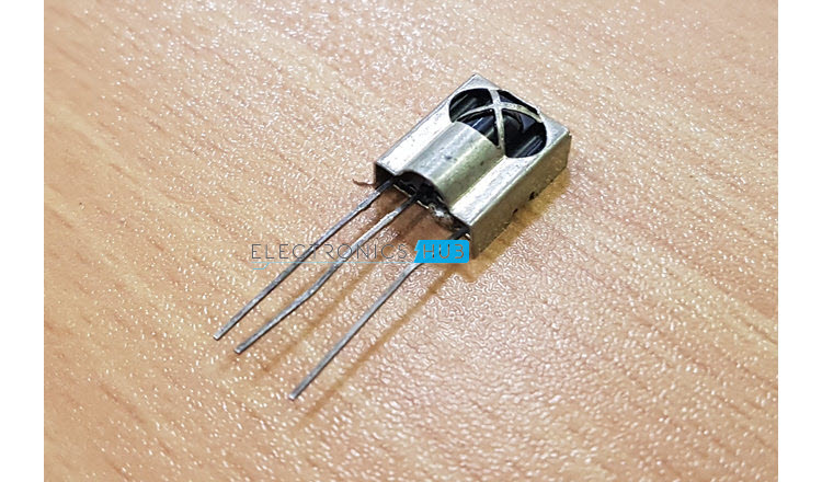
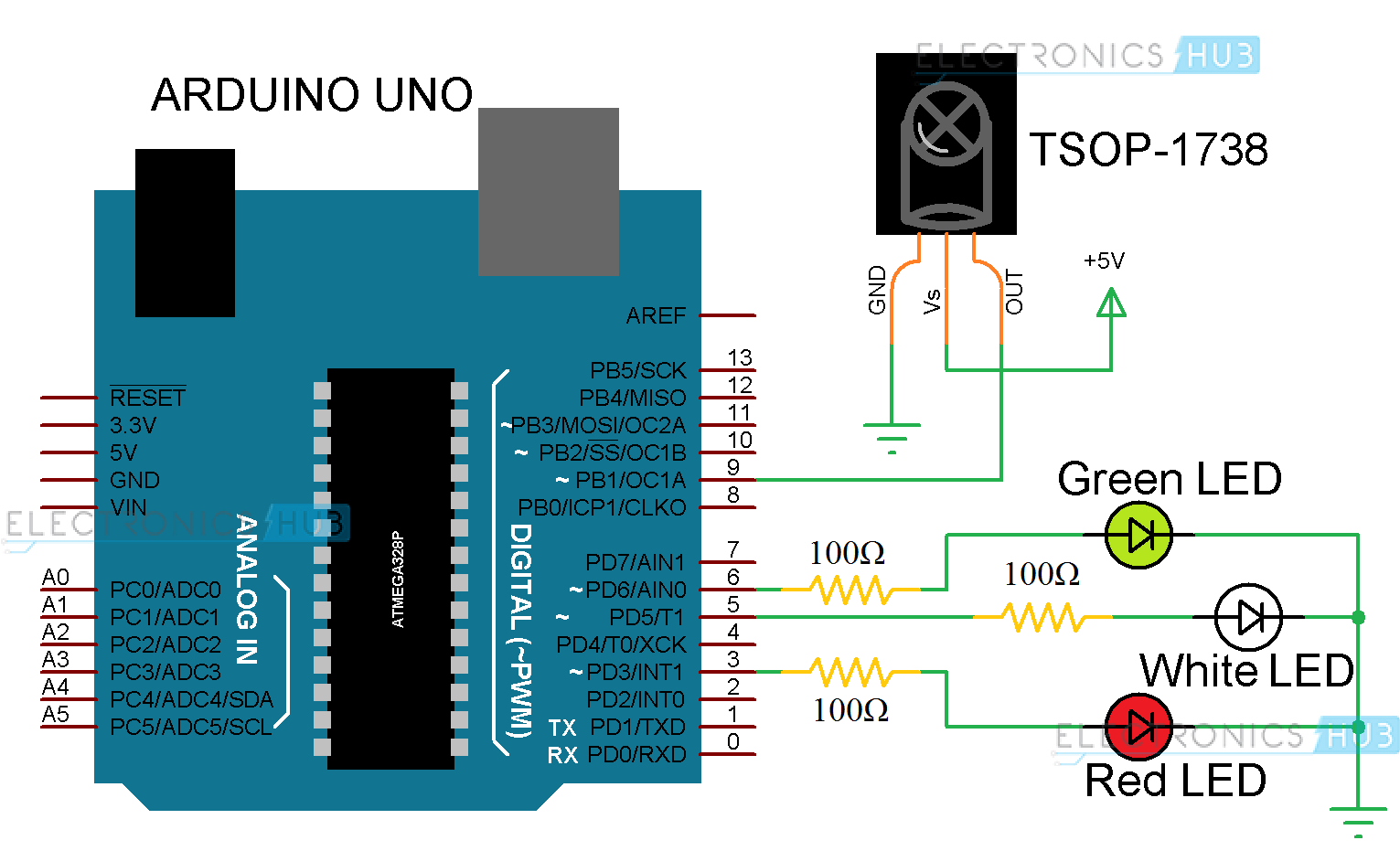
TSOP1738 is a very common and popular IR Receiver, that is tuned for a carrier frequency of 38kHZ. Externally, it consists of three pins namely: GND, Vs and OUT.
Internally, it consists of a Photo Diode, Automatic Gain Control unit, Band Pass Filter and Demodulator. The demodulated output of the TSOP 1738 IR Receiver can be directly decoded by a microcontroller.
Circuit Diagram of Arduino IR Receiver Interface
Components Required
- Arduino UNO
- TSOP1738 IR Receiver
- Red LED
- Green LED
- White LED
- 100Ω Resistors x 3
- Breadboard
- Connecting Wires
- Power Supply
Circuit Design
The OUT Pin of the TSOP1738 IR Receiver is connected with the Digital Pin 9 of the Arduino. Three LEDs (Green, White and Red) are connected to Pins 6, 5 and 3 of Arduino UNO through corresponding current limiting resistors.
The first code is to decode the data from the remote control. We have already seen this code in the Arduino Based Home Automation using TV Remote Project.
Upload this code and get a list of HEX Codes for all the button/keys on your remote.
NOTE: This code and the next code will use the “IRremote” library. You must first download this library from this link and extract the contents to Arduino/libraries directory,
The next code is the main code for the project.
Working
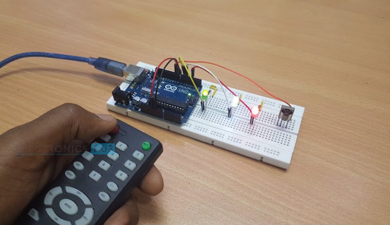
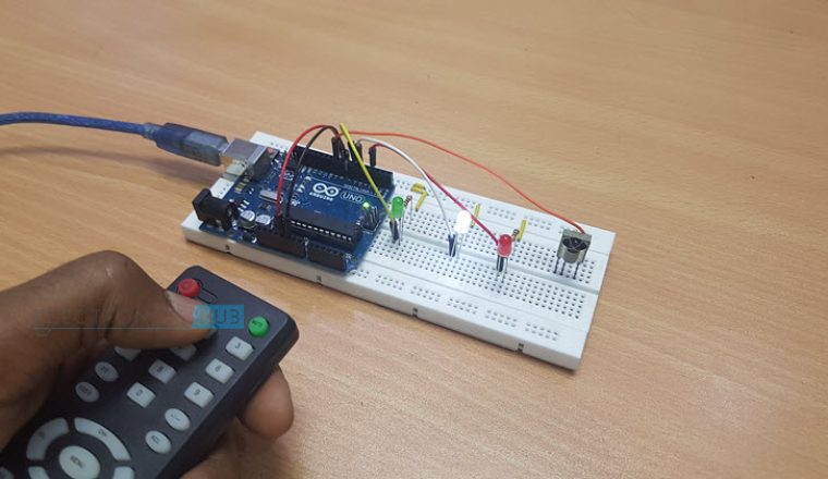
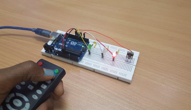
The working of the Arduino IR Receiver Interface project is very simple. This project will demonstrate you how to set up an IR Receiver and an IR Remote on an Arduino Board.
After decoding the data of the remote, each key on the remote can be assigned for a particular task based on the decoded information.
In our case, we have programmed the Arduino to turn ON/OFF all the LEDs if the Power button is pressed. Also, the keys 1, 2 and 3 are used to control the three LEDs individually.
Источник: