


Arduino Internal Pull-Up Resistor Tutorial
Содержание
- Alternate Arduino Internal Pull-Up Resistor Tutorial
- Why doesn’t my button work!?
- Using Pull-Ups to fix Floating
- Conclusion
- 24 thoughts on “ Arduino Internal Pull-Up Resistor Tutorial ”
When hooking up switches or buttons to an Arduino I/O pin, sometimes the results might appear completely random. Sometimes it will appear as though there is a delay from when the button is pressed until the state of the pin actually changes. Other times the pin’s value will seem to randomly fluctuate from HIGH to LOW. Even more maddening might be as your finger gets closer to the switch, the pin’s state changes! The fix to these problems is simple: use the Arduino Internal Pull-up Resistor. Here’s how they can fix this problem and how you can use them with an Arduino board.
Alternate Arduino Internal Pull-Up Resistor Tutorial
AddOhms #15 Video Tutorial covers Pull-Up Resistors, including the Arduino Internal Pull-Up resistor. In the video, I am using a TI LaunchPad with Energia, but the same concept applies to Arduino.
Why doesn’t my button work!?
Consider the following circuit, which is a simple normally-open push-button on a breadboard. It has been wired so that one side is tied to +5V and the other side is connected to Pin 12 of an Arduino Uno. (Make you check with a multimeter to determine which pins are connected together and which are not.)
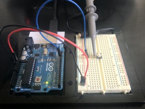
Picture 1: Floating Pushbutton on Breadboard
The code for this switch is very simple. The LED on Pin 13 should light up when Pin 12 is HIGH and be off when Pin 12 is LOW. The expected behavior is that the LED will be OFF whenever the button is not pushed and ON when the button is pushed.
Take a look at this video to see what happens as the button is pushed. The LED’s behavior is not at all predictable! Sometimes it lights up, sometimes it stays on, sometimes it changes just when a finger gets close to it!
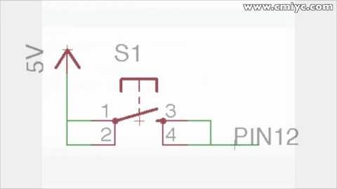
The pin is “Floating.” This schematic shows how the button is wired on the breadboard. What is PIN 12 connected to, when the button is unpressed? Nothing!
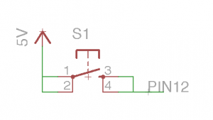
Schematic 1: Schematic of Floating Pin
This means that any signals in the air, such as from nearby electronics, can cause the pin to “float” to either a HIGH or LOW. For example, this waveform from an oscilloscope shows what the pin is doing when nothing is connected.
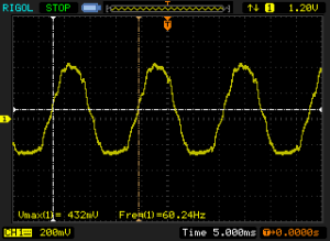
Picture 2: Oscilloscope Screenshot of Floating Pin
This video is the same breadboard circuit but with the oscilloscope waveform visible. As a human finger comes close to the pin, the waveform changes. 60Hz noise from the environment is being coupled into the circuit through the finger, which is what causes the “random” behavior of the input pin.
Great! Now that we understand why the pin randomly changes, how does it get fixed? Easy! Just make your Arduino do exercises… pull-ups in fact!

Using Pull-Ups to fix Floating
The fix for floating pins is to “pull them up” to a known value when the switch is unpressed. This is done with a Pull-Up resistor, as illustrated in the following schematic:
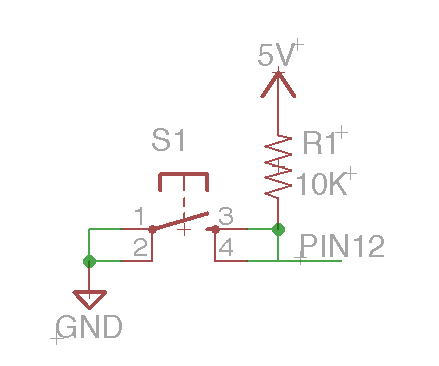
Schematic 2: Pull-Up Resistor of an I/O Pin
Now when nothing is connected, current cannot flow through the resistor. So the Voltage on both legs will be the same. This means the same point where the resistor connects to the switch and Pin 12 will be forced to sit at 5V.
When the button is pressed, that same point will drop to 0V as current starts flowing through the resistor (ohm’s law). Since the resistor is there, you don’t have to worry about a short circuit. In this case, 10Kohms was picked as a relatively large value. The exact value of the resistor does not matter. You want something big enough to limit the amount of current wasted when the button is pressed, but not so big (like 10Mohm that you start having noise problems again.)
A really cool feature of the ATmega chips used by the Arduino platform is that they have these resistors already built into them! All that needs to be done is turn the Arduino Internal Pull-Up resistor on and you get the previous schematic, for free! Here is the new breadboard circuit. Notice that the red jumper wire has changed to yellow. Also, it is no longer connected to 5V but now is connected to GND. That’s the [i]only[/i] difference in the hardware.
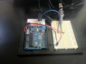
Picture 3: Button Wired with Internal Pull-Up (Blue wire connects to Pin 12 of the Arduino)
It only takes a small change in the code to turn on these incredibly useful internal pull-up resistors. When a Pin has been configured for INPUT with pinMode(), simply use digitalWrite() to write a HIGH to that pin. Here is the same code with a single change:
The combined video of the button working by using the internal pull-up and along with the waveforms on the oscilloscope is shown here.
Conclusion
When using any kind of “open” inputs with an Arduino such as switches, push buttons, reed relays, and some sensors a pull-up resistor is needed for reliable operation. These resistors hold the I/O pin at a known value until the switch forces the I/O pin to a different known value. On each board there are Arduino Internal Pull-Up resistors built-in, they just need to be turned on in the sketch, usually in setup().

Long comments, URLs, and code tend to get flagged for spam moderation. No need to resubmit.
ALL comments submitted with fake or throw-away services are deleted, regardless of content.
Don’t be a dweeb.
Leave a comment Cancel reply
24 thoughts on “ Arduino Internal Pull-Up Resistor Tutorial ”
That resistor is usefull for a sensor input? i mean, talking about a sharp optical sensor “analog singnal”
I don’t see how you would use it for an analog sensor. The only option might be if you are building a voltage divider. However, the value of the internal resistor is not guaranteed. It is anything between 30k and 50k ohms. It would be better to use an external divider.
The only sensor I can see using an internal pull-up is with one that has a digital pin using an “open collector” configuration. (Where something else must pull-up the output signal.)
Really awesome tutorial! I love the simplicity of it. Thanks…looking forward to more videos.
Источник: