


Arduino Due Pinout, Specifications, Schematic datasheet
Содержание
- Introduction to Arduino Due Pinout:
- Arduino Due Pinout in detail:
- Specifications of Arduino DUE :
- Arduino Due microcontroller Datasheet :
- Arduino Due Schematic:
- Arduino Due Dimensions/ Size:
The Arduino Due is one of the most powerful boards of the Arduino series. It was launched by Arduino company in 2012. This board is powered by a 32-bit ARM cortex-M3 processor Atmel SAM3X8E . Arduino Due pinout is explained in detail in this post.
Arduino due board features 52 digital input/output pins , an 84 MHz clock , two micro-USB ports , an SPI header, a JTAG header pins , an ERASE button , and a RESET button . Arduino Due pinout, specifications, schematic, and datasheet is given below.
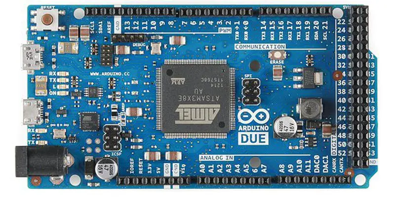
Top view of Arduino Due board
Introduction to Arduino Due Pinout:
Introduction to Arduino Due parts
Arduino Due Microcontroller :
The microcontroller on Arduino Due is based on 32 bit ARM core microcontroller i.e, Atmel SAM3X8E ARM Cortex-M3 CPU
- A 32-bit core , that allows the transfer of 32 bit wide data per a single CPU clock.
- CPU Clock at 84Mhz .
- 96 Kbytes of SRAM .
- 512 Kbytes of Flash memory for code.
- A DMA (Direct Memory Access) controller, that helps the processor to communicate with I/O devices without doing memory-intensive tasks.
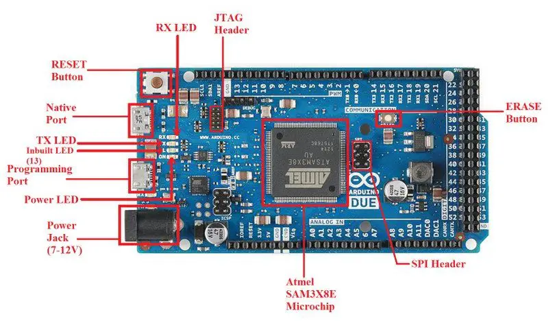
Inbuilt LED (13) : An Inbuilt LED is also present on the board that is connected to pin no 13. This Led can be controlled by switching the pin HIGH or LOW
Power LED : The board comes with a power Led that lit up as soon as the board is connected to a computer.
TX and RX LED : On the board, there are two more LEDs connected to the UART pin.
RESET button : The board comes with a RESET button that can be used to reset the board and begin the execution of the program from the beginning.
ERASE button : The Arduino Due comes with an ERASE button that is used to erase the flash memory of SAM3X.
Arduino Due Pinout in detail:
Arduino Due pinout is shown in two separate images. Pinout image A describes the side pins of the board whereas Pinout image B describes the bottom pins of the board.
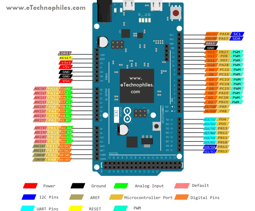 Arduino Due Pinout A (side pins)
  Arduino Due Pinout B (bottom pins)
As shown in the Arduino Due pinout image, the board consists of more than 90 pins in total, 54 of which are digital I/O pins. And out of these 12 are PWM enabled, with 12 analog input pins.
Power pins and ports on Arduino Due board:
USB port : Arduino Due has two micro-USB ports that can be used to power up as well as program the board.
· Programming port : This port is connected to a powerful 8-bit microcontroller Atmel 16U2 , which acts as a USB to serial converter. This port is recommended to use for programming purposes.
· Native port : This port is directly connected to the Atmel SAM3X8E microchip and is used to emulate the USB devices. We can connect external keyboards, mouse, and smartphones to this port.
Vin : This is the input voltage pin, which can be used to power up the Arduino board. When a certain voltage is given via the USB port to power the board, this voltage is reflected at the Vin pin.
Power jack : A barrel jack or 7-12V DC Power Jack can be used to power the Arduino board. An adapter is plugged into the power jack. The Arduino Due board can be powered by an adapter that ranges between 5-20 volts but the manufacturer recommends keeping it between 7-12 volts.
Note: Above 12 volts, the board might overheat whereas voltage below 7 volts might not be sufficient to power the Arduino Due board.
3v3 : The 3.3V pin generates an output voltage of 3.3v.
5v : The 5V pin generates regulated 5v output for the externally connected components. The power source of the 5V pin for the Arduino Due board is a USB connector and the Vin.
GND: Five ground pins are available on the Arduino Due board.
Digital Pins on Arduino Due Pinout:
- The Arduino Due board comes with 52 digital I/O pins that can be used as an input or output. These pins operate at 5 volts.
- The Arduino Due digital pins like every other Arduino board can read one of the two states: when the electric signal is present and when it is absent. This type of input is usually known as digital type (or binary) and these states are referred to as HIGH which is 1 or LOW which is 0.
PWM pins on board:
- The 12 pins from the set of digital pins are PWM (Pulse Width Modulation) pins which are numbered as 2,3,4,5,6,8,9,10,11,12, and 13.
- Each PWM pin provides 8-bit PWM output.
- To generate the PWM output, syntax “analogwrite(PWM Pin, PWM value)” is used. PWM output value varies between 0 (0 volts) and 255 (5 volts).

Analog Input pins:
- These pins are used to read the value coming from the analog sensor connected to the board.
- The Arduino Due consists of 12 analog inputs, labeled as AX (where X is pin no. ranging from 0-11). All of these pins can also be utilized as digital I/O pins.
- Each of the analog pins is connected to an inbuilt ADC of 12-bit (i.e., 4096 different values) resolution.
Digital to Analog converter pins on Arduino Due pinout:
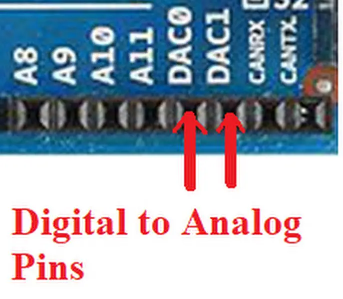
Arduino Due DAC pins
Along with the Analog input pins, the board also consists of two-channel of true analog outputs with 12-bits resolution (4096 levels) that can be controlled with the analogWrite() function. One application of these pins can be to create an audio output using the Audio library.
I2C or TWI pins:
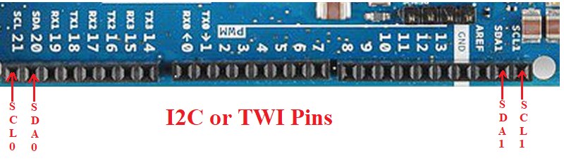
Arduino Due I2C or TWI pins
I2C or TWI is the two-wire serial communication protocol. The I2C protocol stands for Inter-Integrated Circuits. The protocol uses two pins for sending and receiving clock data as well as serial data: a serial clock (SCL) pin and a serial data (SDA) pin.
- SCL-It stands for Serial Clock. It is used for sending the clock data between the devices. It is also used for synchronization purposes; this pin is provided by the master device.
- SDA-It stands for Serial Data. This pin is operated by both the slave and master device for purpose of sending and receiving the data. That’s why it is also called a data line, while SCL is known as a clock line.
UART or SERIAL Pins:
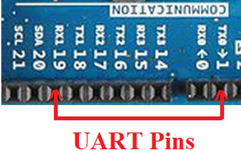
Arduino Due UART pins
UART pins are used for serial communication. 0 (RX) to receive the data, and 1 (TX) to transmit (TX) TTL serial data using the Atmel SAM3XBE advanced hardware serial capabilities. There are 4 UART or Serial ports on Arduino Due pinout.
JTAG header:
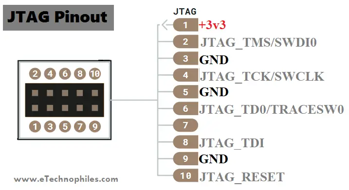
JTAG pinout
JTAG stands for Joint Test Action Group . JTAG is used for a debugging, programming, and testing interface typically found on all modern microcontrollers. All the microcontrollers with the JTAG interface can be programmed, tested, or debugged using a single connector on a PC board.
SPI header:
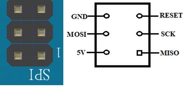
Arduino Due SPI pins
Unlike other Arduino boards, the SPI pins in the Arduino Due board are broken out on the central 6-pin ICSP header , which makes it physically compatible with the Uno, Leonardo, and other Arduino devices. These SPI pins can only be used for communication purposes with other SPI devices, not for programming the SAM3X microchip using the In-Circuit-Serial-Programming technique.
- It stands for Serial Peripheral Interface.
- These pins are used to send the serial data between the microcontrollers and one or more peripheral devices efficiently.
- The board consist of 4 SPI pins:
- SCK (Serial Clock)
- SS (Slave Select)
- MOSI (Master Out Slave In)
- MISO (Master In Slave Out)
Specifications of Arduino DUE :
| Microcontroller | AT91SAM3X8E |
| Operating Voltage | 3.3V |
| Input Voltage (recommended) | 7-12V |
| Input Voltage (limits) | 6-20V |
| Digital I/O Pins | 54 (of which 12 provide PWM output) |
| Analog Input Pins | 12 |
| Analog Outputs Pins | 2 (DAC) |
| Total DC Output Current on all I/O lines | 130 mA |
| DC Current for 3.3V Pin | 800 mA |
| DC Current for 5V Pin | 800 mA |
| Flash Memory | 512 KB all available for the user applications |
| SRAM | 96 KB (two banks 64KB and 32KB) |
| Clock Speed | 84 MHz |
Arduino Due microcontroller Datasheet :
To download the datasheet of the SAM3A microcontroller present on Arduino Due, click here.
Arduino Due Schematic:
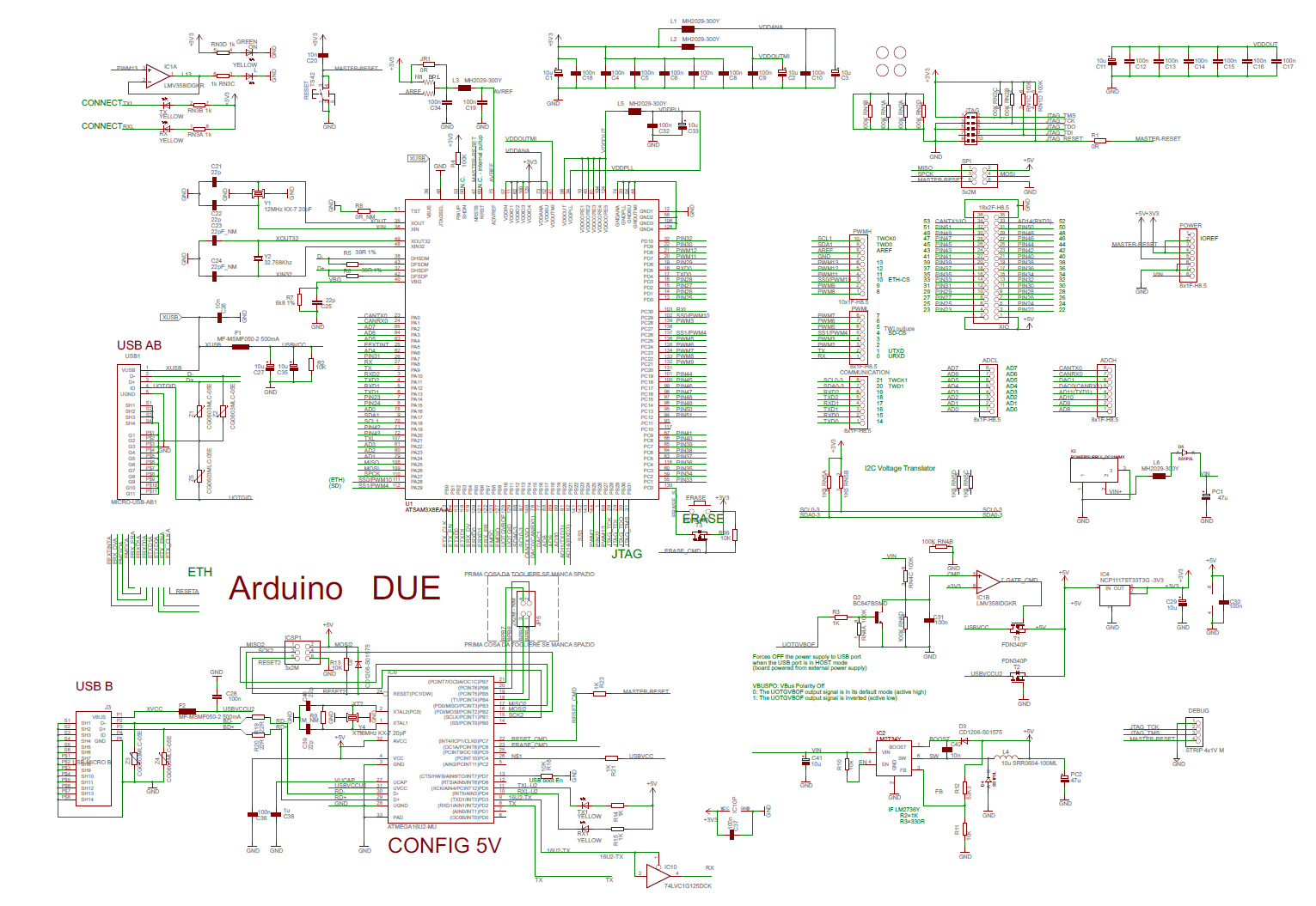
Arduino Due Schematic
To download the schematic of the Arduino Due board, click here.
Arduino Due Dimensions/ Size:
Length : 101.6 mm
Height : 12.83 mm
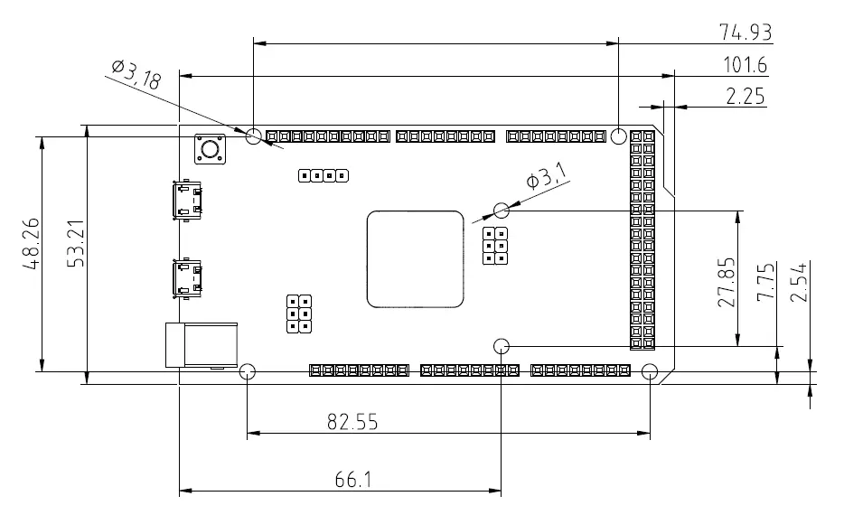
Dimensions of Arduino Due
Источник: