


ARM Programming
Содержание
- What is an ARM?
- Bootloaders
- JTAG and SWD
- Programmers and J-Link Software
- Hardware Hookup
- AVR Studio
- Troubleshooting
- Resources and Going Further
SparkFun has been a fan of Arduino for a long time. We’ve programmed ATMega328s (and 168s, and 8s before that), written tutorials, and hacked all sorts of fun projects. But now the market is maturing and we are looking at a lot more ARM chips. One advantage of the newer chips is that they generally do not need a USB-to-serial adapter; instead they have USB built in (at least the ones we are using do). You still need to add a bootloader to use them with Arduino, and since ARM programmers are also a little more complicated than AVR programmers you’ll want to invest in a stand alone programmer instead of trying to use the Uno you have laying around.
A few ARM boards:
 |
 |
 |
 |
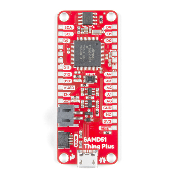 |
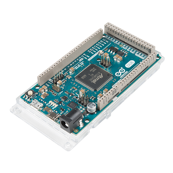
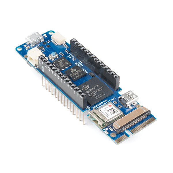
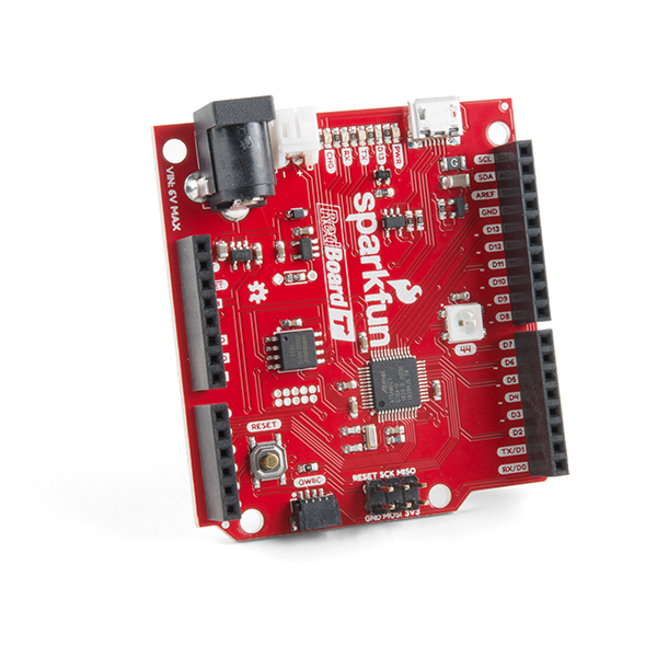
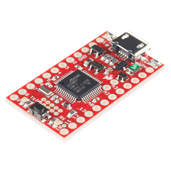
| The Due: Arduino’s first ARM board | MKR Vidor 4000: One of Arduino’s newer Arm boards | RedBoard Turbo: One of SparkFun’s newer boards | SAMD21 Dev Mini: One of SparkFun’s ARM boards | SAMD51 Thing Plus board: SparkFun’s newest ARM board |
Required Materials
To follow along with this tutorial, you will need the following materials. You may not need everything though, depending on what you have. Add it to your cart, read through the guide, and adjust the cart as necessary.
Suggested Reading
If you aren’t familiar with the following concepts, we recommend checking out these tutorials before continuing.
PCB Basics
Installing an Arduino Bootloader
Installing Arduino IDE
Integrated Circuits
What is an ARM?
Let’s start with what an ARM processor is. They are used in everything from the Redboard Turbo to the Raspberry Pi to most cellphones, but that’s a large range of performance. ARM is actually a unique business model. Arm Holdings does the design work for the cores and holds the patents/copyright/other legal things and then licenses the design out. The cores are then put into CPUs, microcontrollers, SOCs (System on Chip), etc. A company might decide they want to build a camera that uses the ARM core. They can license the core, maximize power efficiency, add some silicone for the camera sensor interface, and build the entire system onto a chip.
If you look around you’ll actually see quite a few naming conventions. The v7 architectures lists 3 different profiles:
- Cortex-A: the Application profile
- Cortex-R: the Real-time profile
- Cortex-M: the Microcontroller profile
We are going to be looking at Cortex-Ms. The Cortex M0/M0+ and M1 are actually from the v6 architecture and can be considered a subset for the v7 profile. All that to say that we are going to be looking at programming the SamD21 on our Redboard Turbo (and other boards) as well as the SamD51 on the Thing Plus. The SAMD21 is an ARM Cortex-M0, where the SAMD51 is an ARM Cortex-M4F.
Bootloaders
A bootloader is a small piece of code that looks at the programming port (in this case USB) to see if there is new code coming in. If there is, then it takes the code and puts it in a predetermined location. If there isn’t, then it runs the code currently at that location.
Most Arduino boards have a bootloader that allows us to upload code over a USB port (or UART Serial connection). This way, once the bootloader is installed, we can program the board much easier. But sometimes we want to change the function of the bootloader, install a bootloader on a brand new board, or just skip the bootloader and install our code directly (makes it harder for other people to change the code on, say, a commercial product).
The bootloader we recommend using is the UF2 bootloader. You can go here for more information on UF2 bootloaders, or click on the button below to go to SparkFun’s SAMD Bootloaders GitHub Repo:
Whether you use the UF2 bootloader or another bootloader, you’re going to have to download the file. Make sure the file you download is compatible with the board/configuration you are using. Check out our GitHub Respository for the SAMD bootloaders; the Turbo bootloader should work with these boards (you want the *.bin file).
JTAG and SWD
Joint Test Action Group
JTAG stands for Joint Test Action Group (the group who defined the JTAG standard) and was designed as a way to test boards. JTAG allows the user to talk to the bits and pieces of the microcontroller. In many cases, this involves giving them a set of instructions or programming the board. The JTAG standard defines 5 pins:
- TCK: Test Clock
- TMS: Test Mode Select
- TDI: Test Data-In
- TDO: Test Data-out
- TRST: Test Reset (Optional)
The reduced pin count JTAG definition really only consists of 2 pins:
- TMSC: Test Serial Data
- TCKS: Test Clock
The 20 pin connector you see on some programmers was designed for JTAG and all those extra pin can be used for power, ground, and other things. While JTAG does not define a physical pin layout, there are a few common options. The 20 pin connector you see on Segger's J-Link EDU Base and Base Compact programmer is a good example.

Serial Wire Debug
Serial Wire Debug (SWD) is really just a modification/implementation of JTAG specifically for ARM processors. SWD puts the 2 pins (SWDIO and SWCLK) on top of the JTAG pins allowing a user to use either JTAG or SWD without the need to breakout more pins.

Programmers and J-Link Software
SparkFun now carries 3 different ARM programmers from Segger. If you are just getting started and don’t plan on making any money off your project, then the EDU Mini is a great place to start. If you want something a bit more powerful, the J-Link Base EDU is a good option. If you are planning on making money, you cannot use the EDU versions, in which case I recommend the Base Compact that we carry. This is the cheapest Segger ARM programmer without an EDU license. There are plenty of higher end programmers as well, but based on their price, you are only going to grab those if you know exactly what features you need from them. But don’t worry, all these are more than capable of programming our boards.

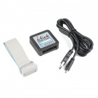
J-Link BASE Compact Programmer
Compact J-Link programmer for programming any ARM microconroller.
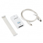
J-Link EDU Base Programmer
J-Link programmer for programming any ARM microconroller. Comes with an educational/ non-commercial license.
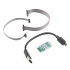
J-Link EDU Mini Programmer
Tiny J-Link programmer for programming any ARM microconroller. Comes with an educational/ non-commercial license.
First step is to download the J-Link Software. This software is good for updating the firmware on the programmers. Go ahead and open the Jlink Configurator and see if your programmer needs an update. The J-Link Software packages has a lot of features you can dig into, but we aren’t going to use them. Feel free to play around and explore the software and all the debugging has to offer.
Hardware Hookup
Now it’s time to hook things up. We will need to make sure that SWCLK and SWDIO are both connected to the microcontroller. On some of our larger boards, like the SAMD21 Dev board and the RedBoard Turbo, we managed to get the full 10 pin header. Our footprint shows a small dash where pin 1 goes. If you check the pinout above you’ll notice that the notch goes on the same side as pin 1. You will probably want a 2×5 header to connect the cable to the board (you can either solder it on, or hold it on securely while programming).
| 10 Pin Headers on Various SparkFun Boards | ||
|---|---|---|
 |
 |
 |
| SAMD21 Mini | RedBoard Turbo | SAMD21 Dev |
On other boards such as the ProRF or the SAMD51 Thing Plus you may have to dig into the schematic or board files to find the test points. There is at least one test point on all our boards since we program the boards after they are assembled and need access to them. Programming these might be a bit trickier without a jig, but I recommend holding a pair of jumper wires against the pads while uploading. It should only take a few seconds to program, but might be tricky and require an extra pair of hands.
| Test Pads on the SparkFun SAMD51 Thing Plus Board | |
|---|---|
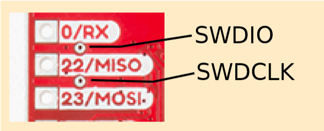 |
 |
| SAMD51 Board with SWDIO above MISO and SWDCLK below MIOS | Back of SAMD51 board showing the 2 testpads |
Tip: Try soldering pins from jumper wires, thin solid core wires, or 0Ω resistors to connect to the test points. We use this trick to program an AVR microcontroller with ICSP pins broken out on test pads similar like the image shown below.
Jumper Wires Used to Help Program an AVR Chip via Test Pads
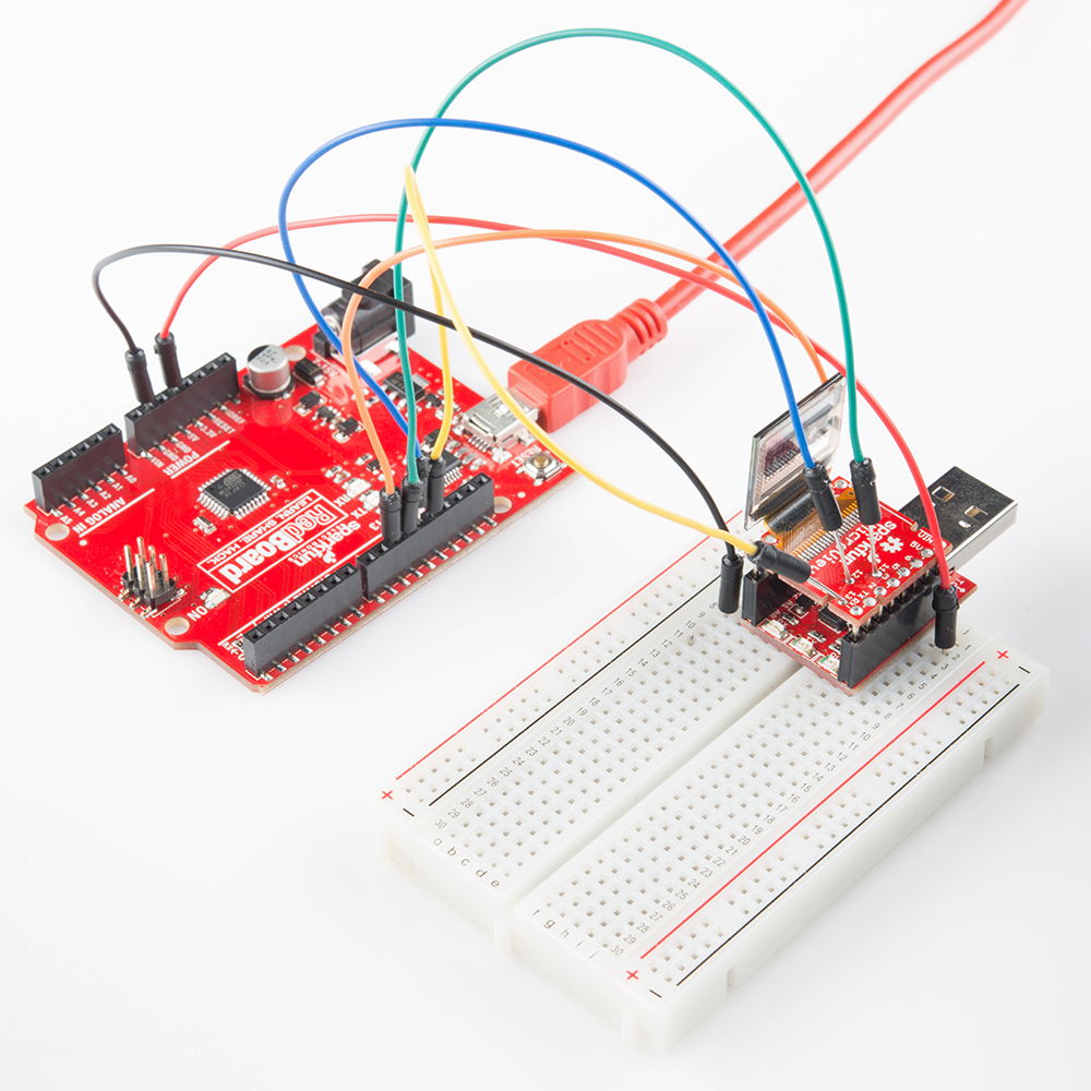
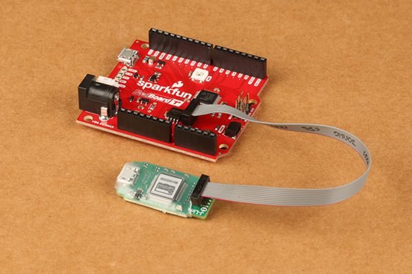
With the 2×5 header soldered into the 10 pin headers, connecting to the RedBoard Turbo is fairly straightforward:
AVR Studio
Now that we’ve gotten everything hooked up it is time to program. There are a few different options for programming. Atmel studio is a great option (assuming you are using an ATMEL ARM processor like the SAMD line). Atmel Studio also lets you write programs in C, and compile your code. The Arduino IDE also lets you compile and download a *.hex file of your code. Make sure you download and install Atmel Studio (Windows 7 or later only)
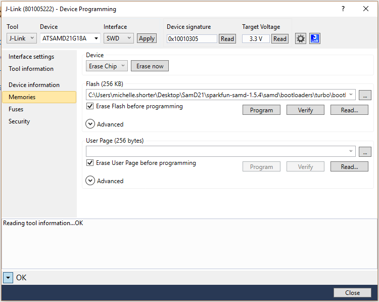
Let’s go ahead and open Atmel Studio. Then we’ll go to Tools and then Device Programming. From the drop down you’ll need to select your programmer as well as your device (you might have to agree to the Terms of Use first). Then hit Apply and it should verify your programmer. Then go ahead and read the Device signature and Target Voltage, this make sure everything is being read correctly. Feel free to look around, you can get quite a bit of Tool Information as well as Device Information.
Next, we’ll go to the Memories tab, you’ll probably want to select "Erase Flash before programming", and then select the location of your bootloader or other code. Hit Program and you should be good to go after a second or 2.
Troubleshooting
Bootloader Protect Fuse Bits
If you get an error when trying to program, check the Fuses tab. On many of our boards we set the bootloader protection to protect from accidental overwriting. Basically this defines the size of the bootloader. Setting this value to 0x07 will set the bootloader size to 0 and allow you to write to that space.

Error Reading Device Signature and Flashing
If you receive the error below:
This may be due to a few things:
- clock speed is too high
- try setting the the programmer to 1/4 of the frequency of the target device
- check the user manual on the programmer and ensure that the pinout matches the target's header pins
- ensure that the solder joints are good
- since the programmer does not provide power, make sure you are providing power to your target device
In this particular case, it was due to the wiring of the 2×5 header on the Atmel JTAGICE3 port. It was different from the 2×5 header on the target device. The latest Atmel JTAGICE has two ports and an adapter to correctly connect to the 2×5 header.
Need Help?
If you need technical assistance and more information on a product that is not working as you expected, we recommend heading on over to the SparkFun Technical Assistance page for some initial troubleshooting.
If you don’t find what you need there, the SparkFun Forums are a great place to find and ask for help. If this is your first visit, you’ll need to create a Forum Account to search product forums and post questions.
Resources and Going Further
Need more information? Check out some of the links below:
Check out these other great tutorials for ARM based boards from SparkFun:
Источник: